lp-505 Rev. 000 Rel. 015 Date 1.7.20
36
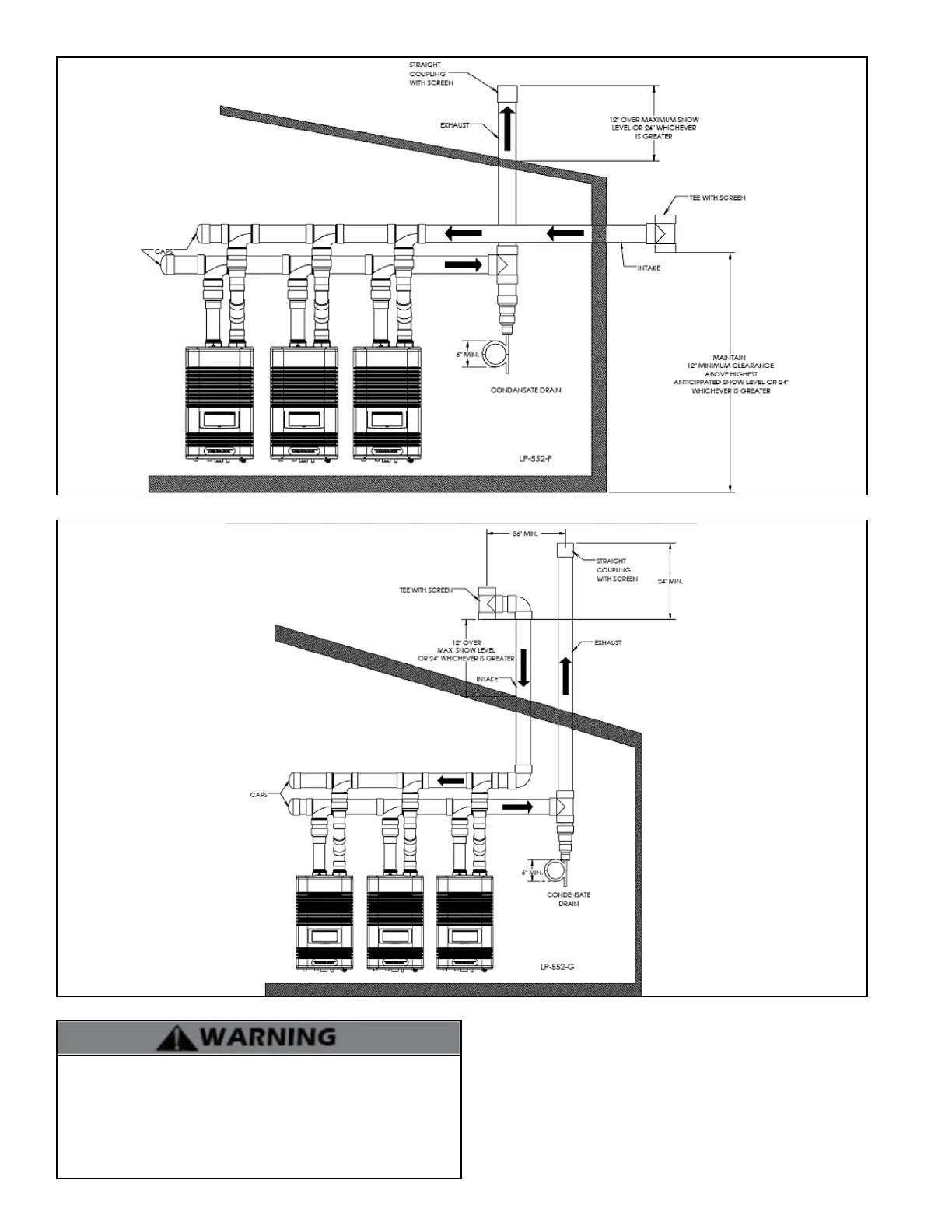
NOTE: This drawing is meant only to demonstrate system venting.
The installer is responsible for all equipment and detailing required
by local codes. For sidewall applications, terminate the outlet on the
exterior wall at least 12” above the ground, or as required by local
building codes. In areas of high snowfall, protect both sidewall and
roof vent terminations from blockage by installing at least 12” above
the maximum anticipated snowfall accumulation.
Figure 29 - Common Vented Units – Unbalanced Venting
Figure 30 - Common Vented Units – Roof Venting
All vent pipes must be glued, properly supported, and the exhaust
pitched a minimum of 1/4” per foot back to the heater to allow
drainage of condensate. When placing support brackets on vent
piping, the rst bracket must be within 1 foot of the water heater
and the balance of 4 foot intervals on the vent pipe. Venting must be
readily accessible for visual inspection from the rst three feet from
the heater.
 Loading...