LP-428 Rev. 6.6.16
28
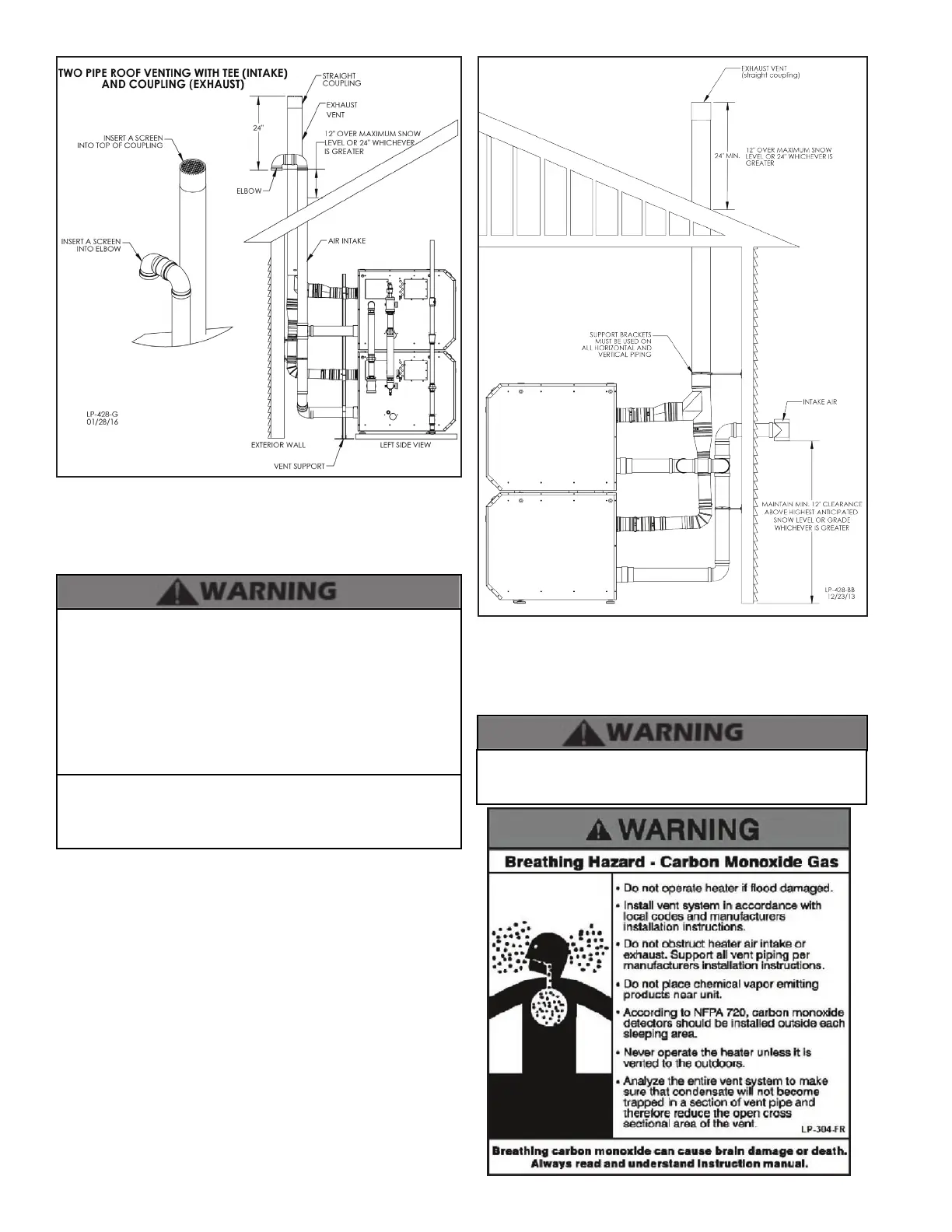
Figure 12 - Venting with Optional Kits (NOT INCLUDED WITH THE
BOILER)
NOTE: These drawings are meant to demonstrate system
venting only. The installer is responsible for all equipment and
detailing required by local codes.
All vent pipes must be glued, properly supported, and the
exhaust must be pitched a minimum of ¼” per foot back to the
boiler to allow drainage of condensate. Exhaust connection
insertion depth should be a minimum of 2 ½” for 1000 models
and 3” for 1700 models. When placing support brackets on vent
piping, the rst bracket must be within 1’ of the appliance and
the balance at 4’ intervals on the vent pipe. Boiler venting must
be readily accessible for visual inspection for the rst three feet
from the boiler.
Take extra precaution to adequately support the weight of vent
pipes terminating through the roof. Failure to properly support
roof terminated vent piping could result in property damage,
serious personal injury, or death due to ue gas leakage.
NOTE: These drawings are meant to demonstrate system
venting only. The installer is responsible for all equipment and
detailing required by local codes.
Figure 13 - Unbalanced Venting - Roof Exhaust and Sidewall
Intake
An unbalanced vent system can be installed ONLY when the
exhaust is in the vertical position. Failure to do so could result
in serious personal injury or death.