LP-454 Rev. 004 Rel. 002 Date 12.1.17
19
Friction Loss Equivalent in Piping and Fittings
Fittings or Piping
Equivalent Feet
3” 4”
90 Degree Elbow* 5’ 3’
45 Degree Elbow 3’ 1’
Coupling 0’ 0’
Air Inlet Tee 0’ 0’
Straight Pipe 1’ 1’
Concentric Kit 3’ N/A
V500 2” Kit N/A N/A
V1000 3” Kit 1’ 1’
V2000 4” Kit 1’ 1’
Table 7 - *Friction loss for long radius elbow is 1 foot less. NOTE: Consult
Polypropylene venting instructions for friction loss and pressure drop
equivalents.
b. For example: If exhaust vent has two 90
o
elbows and 10 feet of
PVC pipe we will calculate:
Exhaust Vent Equivalent Length = (2x3) + 10 = 16 feet.
Further, if the intake pipe has two 90
o
elbows, one 45
o
elbow,
and 10 feet of PVC pipe, the following calculation applies:
Intake Pipe Equivalent Length = (2x3) + 1 + 10 = 17 feet.
Total Equivalent Length = 16 + 17 = 33 feet.
The total equivalent length is 33 feet, well below the maximum
of 200 feet.
c. Eort should be made to keep a minimum dierence in
equivalent length between the exhaust vent and intake pipe.
d. The vent size on the PHP199-119 can also be reduced down
to a 3” vent from a 4” vent in order to accommodate existing
vent sizes. When reducing down to a 3” vent from a 4” vent
on PHP199-119 models, the total length shall not exceed 100
equivalent feet. Vent reduction must begin at the heater.
3. The minimum total equivalent length is 16 feet.
Do not exceed the maximum lengths for vent pipes. Excessive
length could result in heater shutdown and property damage.
F. Exhaust Vent and Intake Pipe Installation
All joints of positive pressure vent systems must be sealed
completely to prevent leakage of ue products into the living
space. Failure to do so could result in property damage, serious
injury, or death.
Failure to provide a minimum total vent length of 16 equivalent
feet could result in property damage and improper product
operation.
Do not reduce the vent size on any model other than the PHP199-
119. Doing so could result in water heater shutdown and property
damage.
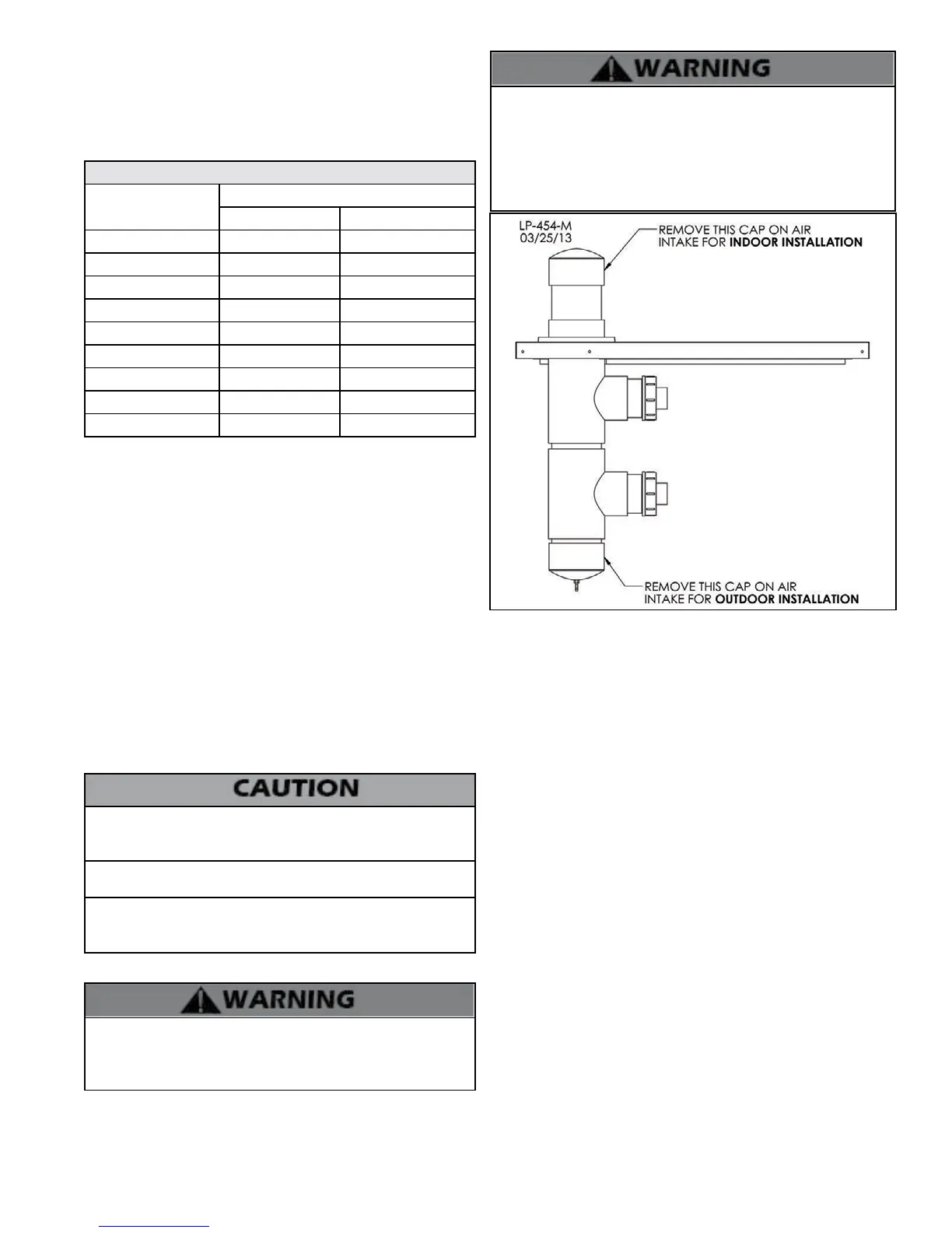
NOTE: Do not block any air openings in the cabinet to ensure proper
cooling and ventilation of components.
When venting in an Indoor Installation: Remove cap installed
outside the water heater cabinet from the air intake and leave the
cap inside the water heater cabinet installed. When venting in an
Outdoor Installation: Remove cap from the air intake inside the
water heater and leave the cap outside the water heater installed.
See Figure 8 for details. Failure to do so could result in property
damage, serious injury, or death.
1. Use only solid PVC, CPVC, or stainless steel pipe or a Polypropylene
vent system approved for use with Category IV appliances.
FOAM CORE PIPING IS NOT APPROVED FOR EXHAUST VENT
APPLICATIONS. Foam core piping may be used on air inlet piping only.
2. Remove all burrs and debris from joints and ttings.
3. When using PVC or CPVC pipe, all joints must be properly cleaned,
primed, and cemented. Use only cement and primer approved for
use with the pipe material. Cement must conform to ASTM D2564
for PVC and ASTM F493 for CPVC pipe. NOTE: DO NOT CEMENT
POLYPROPYLENE PIPE.
4. Ensure the vent is located where it will not be exposed to prevailing
winds.
5. In all roof venting applications, exhaust discharge must point away
from the pitch of the roof.
6. If the exhaust vent is to be terminated in a walled o area (such
as a roof with a parapet wall), ensure the exhaust vent terminates a
minimum of 10’ from nearest wall and extends level with or above the
top of the wall. This will ensure ue gas does does not get trapped and
possibly recirculated into the intake air pipe, which could contaminate
the combustion air.
7. To prevent water leakage, install adequate roof ashing where the
pipe enters the roof.
8. Do not locate vent over public walkways, driveways, or parking lots.
Condensate could drip and freeze, resulting in a slip hazard or damage
to vehicles and machinery.
9. Due to potential moisture build-up, sidewall venting may not be
the preferred venting option. To save time and cost, carefully consider
venting installation and location.
10. Horizontal lengths of exhaust vent must slope back towards the
water heater not less than ¼” per foot to allow condensate to drain
from the vent pipe.
11. The exhaust vent must terminate where vapors cannot make
Figure 8 - Air Intake Instructions
E. Exhaust Vent and Intake Pipe Sizing
1. The exhaust vent and intake pipe size is 4” for all models.
2. The maximum total equivalent length of 4” exhaust vent and
intake pipe should not exceed 200 feet.
a. The equivalent length of elbows, tees, and other ttings are
listed in the Friction Loss Table.