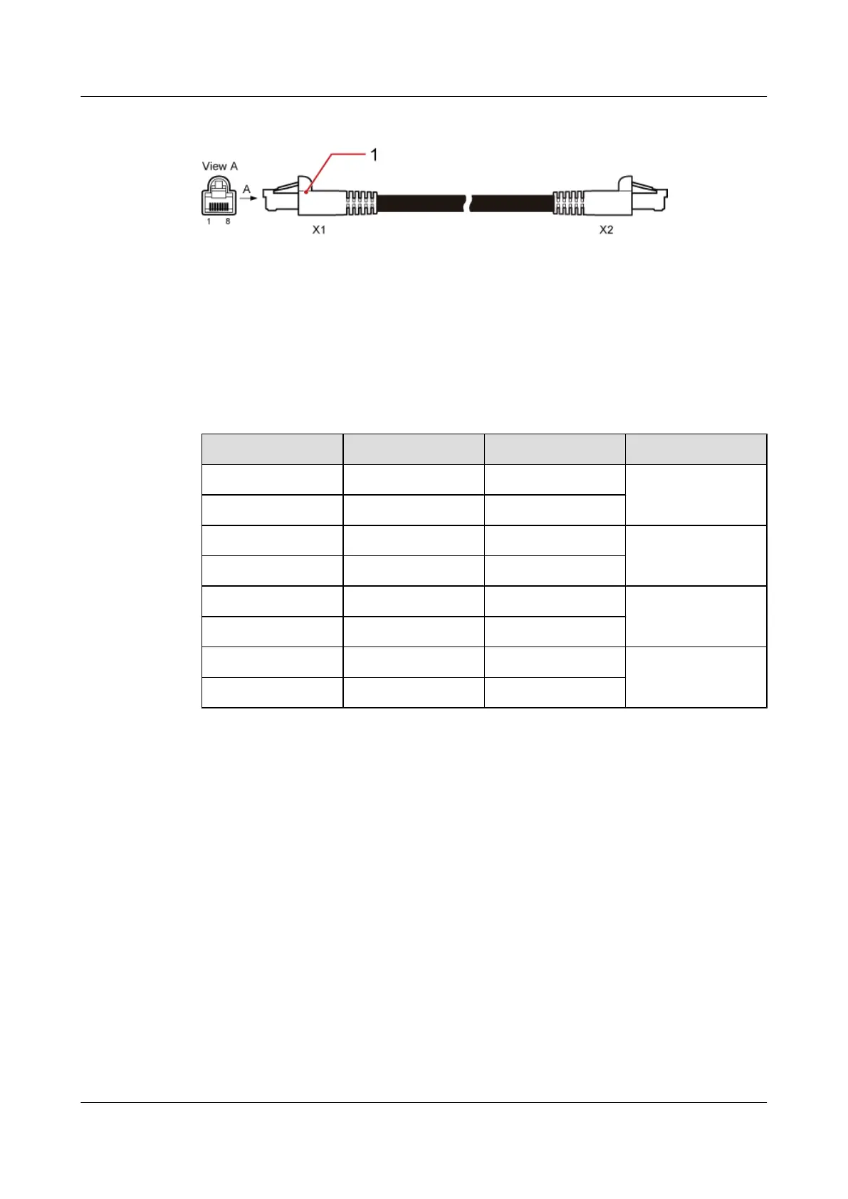
Figure 7-40 PMU 11A monitoring signal cable
(1) RJ45 connector
Cable Description
Table 7-36 describes the pin assignment for the wires of the PMU 11A monitoring signal cable.
Table 7-36 Pin assignment for the wires of the PMU 11A monitoring signal cable
X1 End X2 End Color Type
X1.1 X2.1 White Twisted pair
X1.2 X2.2 Orange
X1.3 X2.3 White Twisted pair
X1.6 X2.6 Green
X1.5 X2.5 White Twisted pair
X1.4 X2.4 Blue
X1.7 X2.7 White Twisted pair
X1.8 X2.8 Brown
7.8.4 HEUB-BBU Monitoring Signal Cable
The HEUB-BBU monitoring signal cable transmits the monitoring information collected by the
HEUB to the BBU.
Exterior
Figure 7-41 shows an HEUB-BBU monitoring signal cable.
BTS3900C (Ver.C)
Hardware Description 7 BTS3900C Cables
Issue 03 (2013-05-27) Huawei Proprietary and Confidential
Copyright © Huawei Technologies Co., Ltd.
166