FusionModule5000 Smart Modular Data Center
Maintenance Guide (ECC800)
Huawei Proprietary and Confidential
Copyright © Huawei Technologies Co., Ltd.
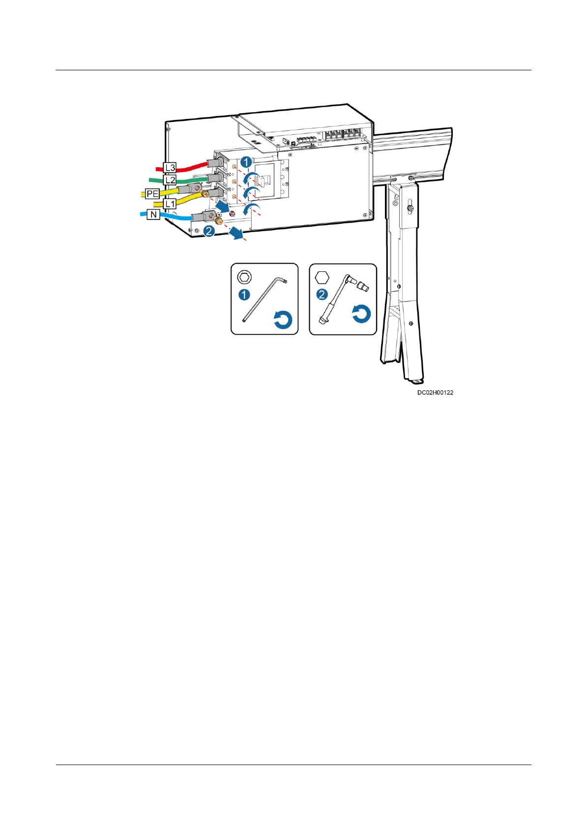
Figure 5-28 Removing cables
Step 8 Remove the connective kit between the faulty general input unit and downstream busbar
trunking unit by referring to Figure 5-24 in 5.1.3.2 Replacing the Busbar Trunking Unit.
Step 9 Remove M6 screws connecting the busbar trunking unit and support using a 10# socket
wrench by referring to Figure 5-25 in 5.1.3.2 Replacing the Busbar Trunking Unit.
Step 10 Take out the faulty general input unit and replace it with the spare one.
Step 11 Secure the busbar trunking part of the general input unit to the base support using M6 screws.
Step 12 Secure the connective kit between the general input unit and downstream busbar trunking unit
by referring to Step 8 in 5.1.3.2 Replacing the Busbar Trunking Unit.
Step 13 Connect the input cables to the general input unit according to the terminal labels in Step 7.
Step 14 Reinstall the power distribution unit by referring to 5.1.3.1 Replacing the Power Distribution
Unit.
Step 15 Turn on the upstream switch along the new main way.
Step 16 Turn on the switch of the general input unit.
Step 17 Turn on the power distribution units and downstream switches corresponding to the load.
----End