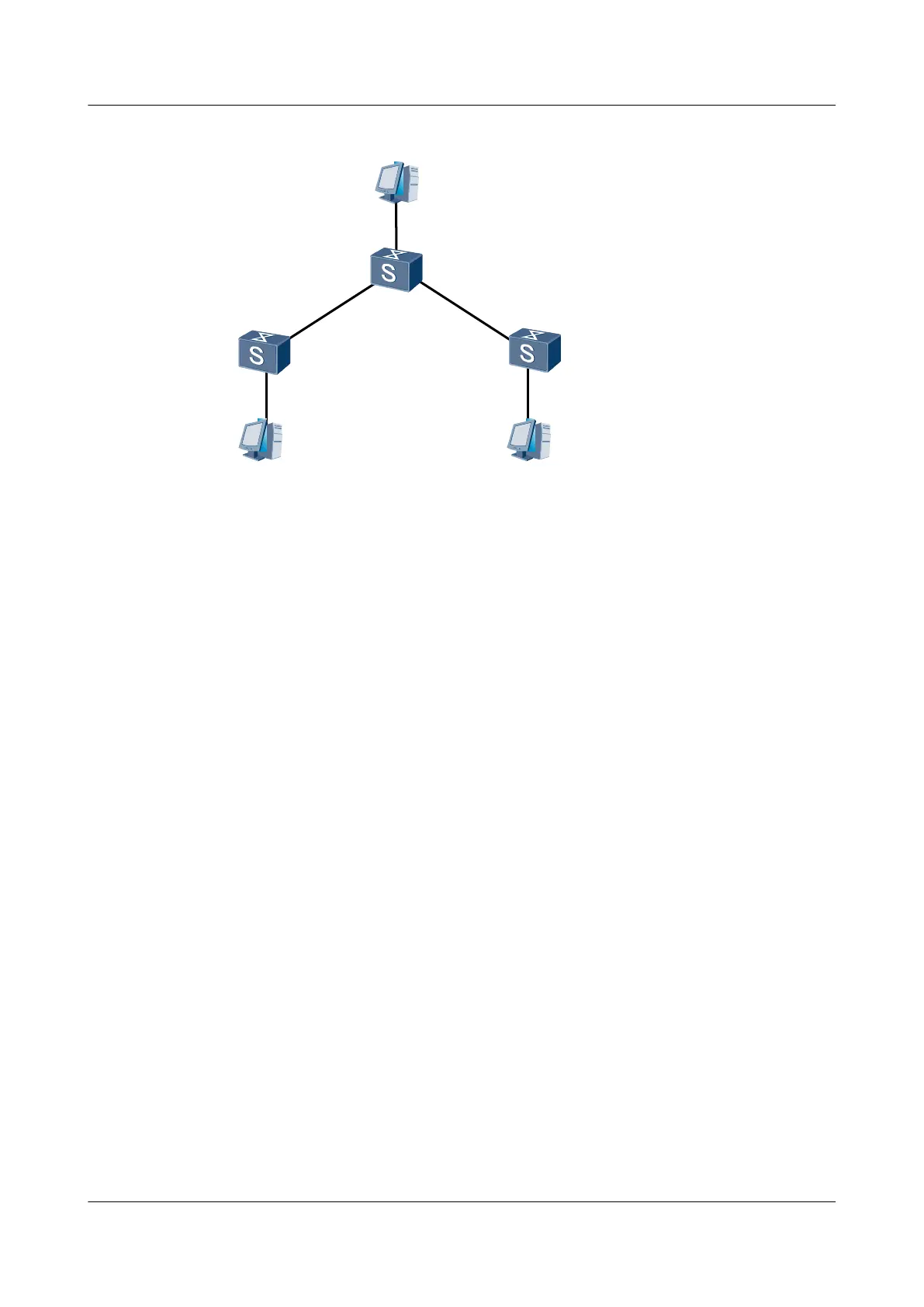
Figure 1-1 Networking diagram for configuring IPv4 static routes
Switch A
Switch B
XGE 0/0/1
XGE 0/0/1
XGE 0/0/2
XGE 0/0/1
XGE 0/0/2XGE 0/0/2
XGE 0/0/3
PC2
PC1 PC3
1.1.2.2/24
1.1.1.2/24
1.1.3.2/24
Switch C
Switch Interface VLANIF Interface IP Address
SwitchA XGE 0/0/1 VLANIF 10 1.1.4.1/30
SwitchA XGE 0/0/2 VLANIF 30 1.1.1.1/24
SwitchB XGE 0/0/1 VLANIF 10 1.1.4.2/30
SwitchB XGE 0/0/2 VLANIF 20 1.1.4.5/30
SwitchB XGE 0/0/3 VLANIF 40 1.1.2.1/24
SwitchC XGE 0/0/1 VLANIF 20 1.1.4.6/30
SwitchC XGE 0/0/2 VLANIF 50 1.1.3.1/24
Configuration Roadmap
The configuration roadmap is as follows:
1. Create a VLAN to which each interface belongs.
2. Assign an IP address to each VLANIF interface.
3. Configure a default IP gateway on each host.
4. Configure static routes and default routes on each switch.
Data Preparation
To complete the configuration, you need the following data:
l The IDs of the VLANs to which the interfaces belong are shown in Figure 1-1.
l The VLANIF interfaces and the IP addresses of the hosts are shown in Figure 1-1.
l The next hop address of the default route on Switch A is 1.1.4.2.
l The destination address of Switch B is 1.1.1.0, and the next hop address of the static route
is 1.1.4.1.
S6700 Series Ethernet Switches
Configuration Guide - IP Routing 1 IP Static Route Configuration
Issue 01 (2012-03-15) Huawei Proprietary and Confidential
Copyright © Huawei Technologies Co., Ltd.
11

 Loading...