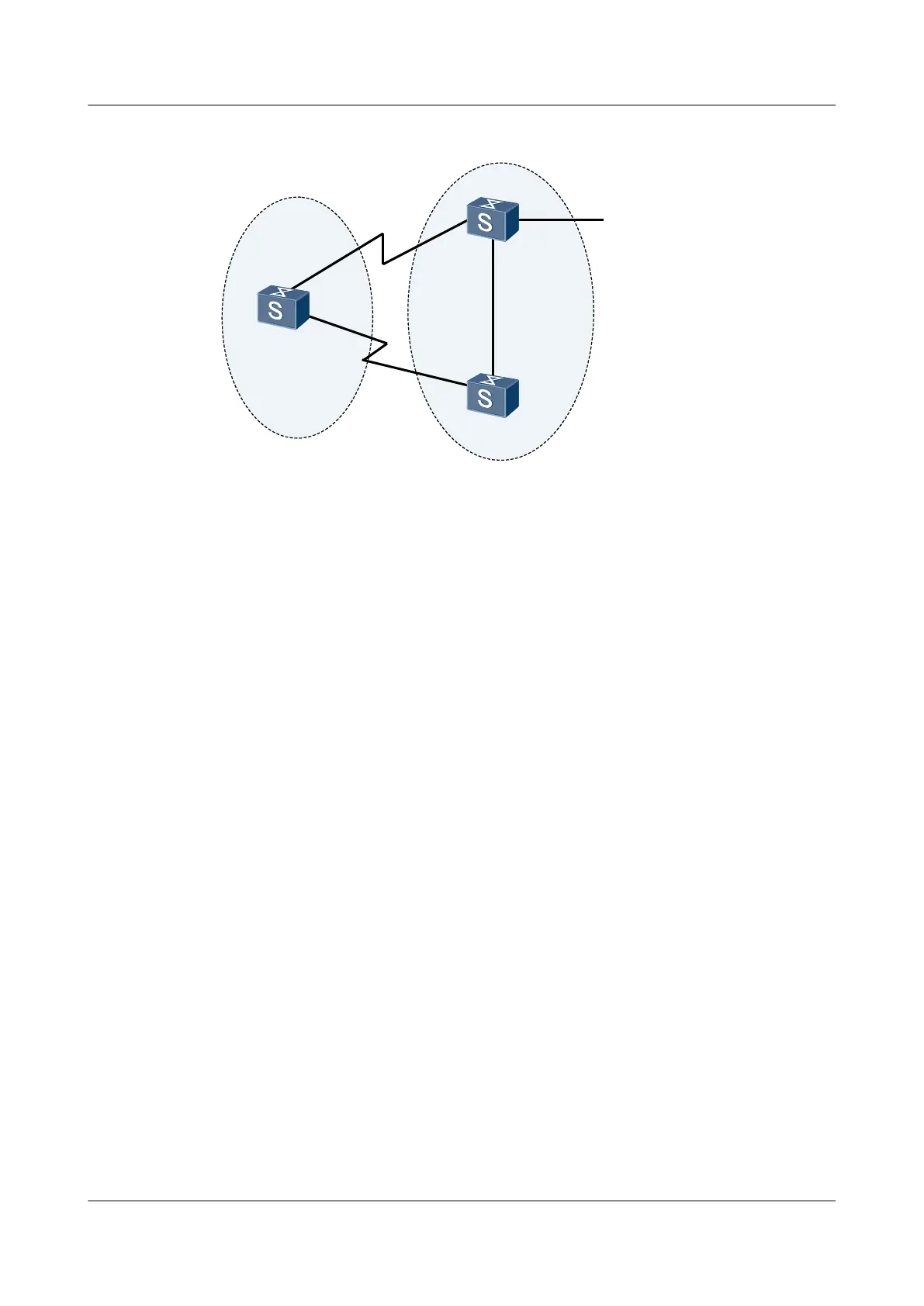
Figure 7-11 Networking diagram for configuring BFD for BGP
SwitchA
XGE0/0/1
XGE0/0/2
AS 200
AS 100
XGE0/0/2
XGE0/0/3
XGE0/0/1
XGE0/0/1
XGE0/0/2
EBGP
EBGP
IBGP
SwitchB
SwitchC
switch Interface VLANIF interface IP address
SwitchA XGigabitEthernet0/0/1 VLANIF 10 200.1.2.1/24
SwitchA XGigabitEthernet0/0/2 VLANIF 20 200.1.1.1/24
SwitchB XGigabitEthernet0/0/1 VLANIF 30 9.1.1.1/24
SwitchB XGigabitEthernet0/0/2 VLANIF 20 200.1.1.2/24
SwitchB XGigabitEthernet0/0/3 VLANIF 40 172.16.1.1/24
SwitchC XGigabitEthernet0/0/1 VLANIF 10 200.1.2.2/24
SwitchC XGigabitEthernet0/0/2 VLANIF 30 9.1.1.2/24
Configuration Roadmap
The configuration roadmap is as follows:
1. Configure basic BGP functions on each switch.
2. Configure MED attributes to control the route selection.
3. Enable BFD on Switch A and Switch B.
Data Preparation
To complete the configuration, you need the following data:
l Router IDs and AS numbers of Switch A Switch B, and Switch C
l Peer IP address detected by BFD
l Minimum interval for sending BFD control packets, minimum interval for receiving BFD
control packets, and local detection multiplier
S6700 Series Ethernet Switches
Configuration Guide - IP Routing 7 BGP Configuration
Issue 01 (2012-03-15) Huawei Proprietary and Confidential
Copyright © Huawei Technologies Co., Ltd.
482

 Loading...