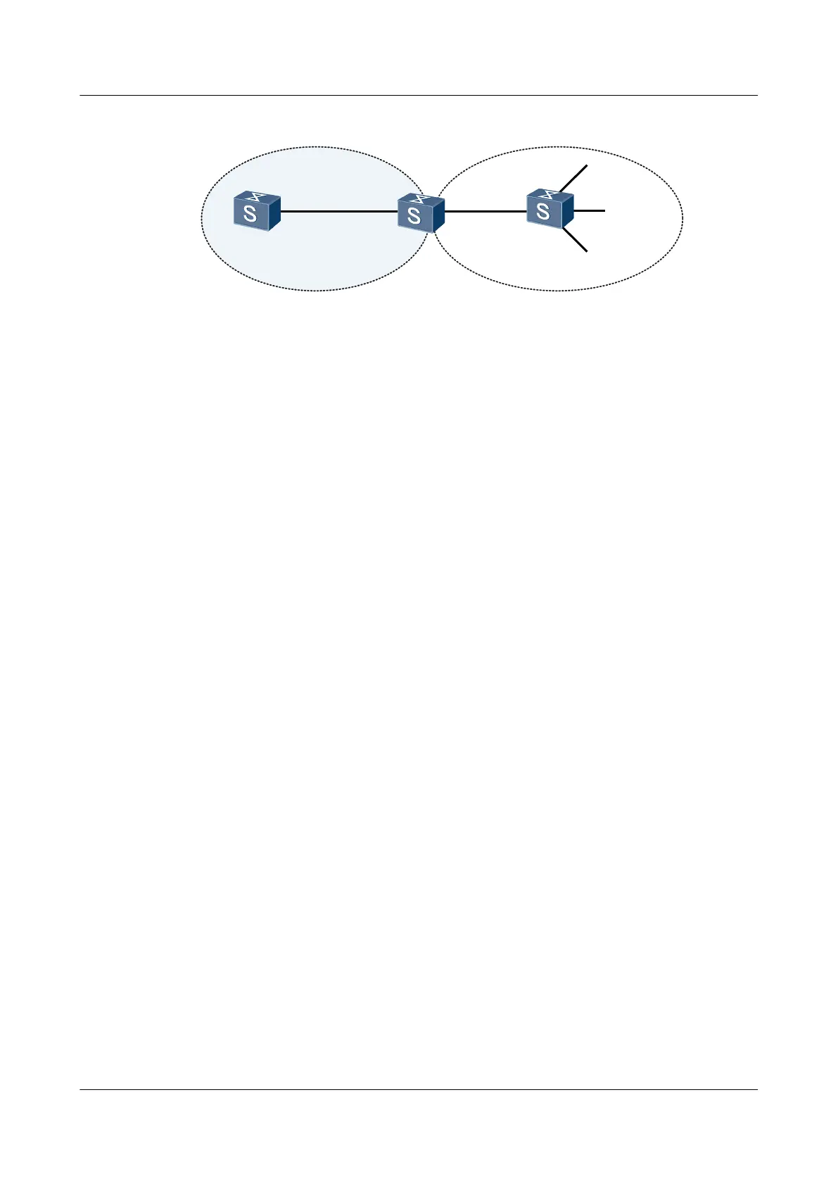
Figure 10-2 Networking diagram of applying a routing policy for imported routes
Switch A
XGE0/0/1
XGE0/0/1
XGE0/0/2
XGE0/0/1
XGE0/0/4
XGE0/0/2
XGE0/0/3
OSPF
IS-IS
Switch B
Switch C
Switch Interface VLANIF Interface IP Address
SwitchA XGE 0/0/1 VLANIF 10 192.168.1.1/24
SwitchB XGE 0/0/1 VLANIF 10 192.168.1.2/24
SwitchB XGE 0/0/2 VLANIF 20 192.168.2.2/24
SwitchC XGE 0/0/1 VLANIF 20 192.168.2.1/24
SwitchC XGE 0/0/2 VLANIF 30 172.17.1.1/24
SwitchC XGE 0/0/3 VLANIF 40 172.17.2.1/24
SwitchC XGE 0/0/4 VLANIF 50 172.17.3.1/24
Configuration Roadmap
The configuration roadmap is as follows:
1. Create the ID of the VLAN to which each interface belongs.
2. Assign an IP address to each VLANIF interface.
3. Configure basic IS-IS functions on Switch-B and Switch-C.
4. Configure OSPF on Switch-A and Switch-B and import IS-IS routes.
5. Configure a routing policy on Switch-B and apply the routing policy when OSPF imports
IS-IS routes, and verify the routes.
Data Preparation
To complete the configuration, you need the following data:
l The IS-IS level of Switch-C is Level-2. The system ID is ID 0000.0000.0001. The IS-IS
level of Switch-B is Level-2. The system ID is ID 0000.0000.0002. The area number of
Switch-B and Switch-C is 10.
l Switch-A and Switch-B are located in Area 0, that is, the backbone area.
l Configure the names of the filtering list and IP prefix list. The cost of the route 172.17.1.0/24
is 100 and the tag of the route 172.17.2.0/24 is 20.
Configuration Procedure
1. Create a VLAN to which each interface belongs.
The configuration details are not mentioned here.
S6700 Series Ethernet Switches
Configuration Guide - IP Routing 10 Routing Policy Configuration
Issue 01 (2012-03-15) Huawei Proprietary and Confidential
Copyright © Huawei Technologies Co., Ltd.
622

 Loading...