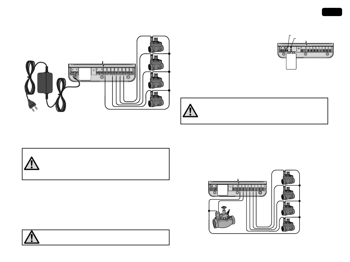
5. Indoor model: route transformer cable through the left side of the
controller and connect the wires to the two screws marked AC.
WATER DAYS
SEASONAL ADJUSTMENT
WATER DAYS
SEASONAL ADJUSTMENT
Valve Common Wire
Connect the Two
Transformer Wires to
the Two AC Terminals
Valve 1
Valve
2
Valve 3
Valve 4
Valve
Wires
6
54321PC
SEN
RST
AC
9 V Battery
WATER DAYS
SEASONAL ADJUSTMENT
WATER DAYS
SEASONAL ADJUSTMENT
6
54321PC
SEN
RST
AC
9 V Battery
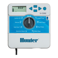
Battery Compartment
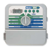
Valve Common Wire
Valve 1
Valve 2
Valve 3
Valve 4
Valve
Wires
Master Valve
Master Valve Wire
WATER DAYS
SEASONAL ADJUSTMENT
WATER DAYS
SEASONAL ADJUSTMENT
6
54321PC
SEN
RST
AC
9 V Battery
CONNECTING THE BATTERY
Connect a 9-volt alkaline battery (not
included) to the battery wire clip located in
the lower left-hand side of the controller.
The battery will allow you to program the
controller without AC power. However, the
battery will not be able to activate any of
the station valves. AC power must resume
before watering will continue.
CONNECTING A MASTER VALVE
NOTE: Complete this section only if you have a master valve
installed. A master valve is a “normally closed” valve
installed at the supply point of the main line that opens only
when the controller initiates a watering program.
1. At the Master Valve, attach the common wire to either solenoid
wire of the valve. Attach a separate control wire to the remaining
solenoid wire.
2. The common wire will still go to the screw slot marked C. The ad-
ditional wire coming from the master valve will go in the screw slot
marked P.
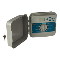
Outdoor model: transformer wires are already connected to the
AC slots so all that is required is to connect primary power to the
junction box from a power source.
E – High Voltage Wiring Compartment (Outdoor Model only)
NOTE: Outdoor model is water and weather resistant.
Connecting the outdoor EC to the primary power should
only be done by a licensed electrician following all
local codes. Improper installation could result in shock
or fire hazard.
Route AC power cable and conduit through the ½" (13 mm) conduit
opening on the the left side of the bottom of the cabinet and connect
one wire to each of the two wires inside the junction box. Do not
connect high voltage wires to the AC terminals inside the controller.
Wire nuts are provided to make these wire connections. Note: For -E
models, connect the wires to the AC terminal strip located inside the
junction box.
Do not plug transformer into power source until the con-
troller is mounted and all valves have been connected.
4