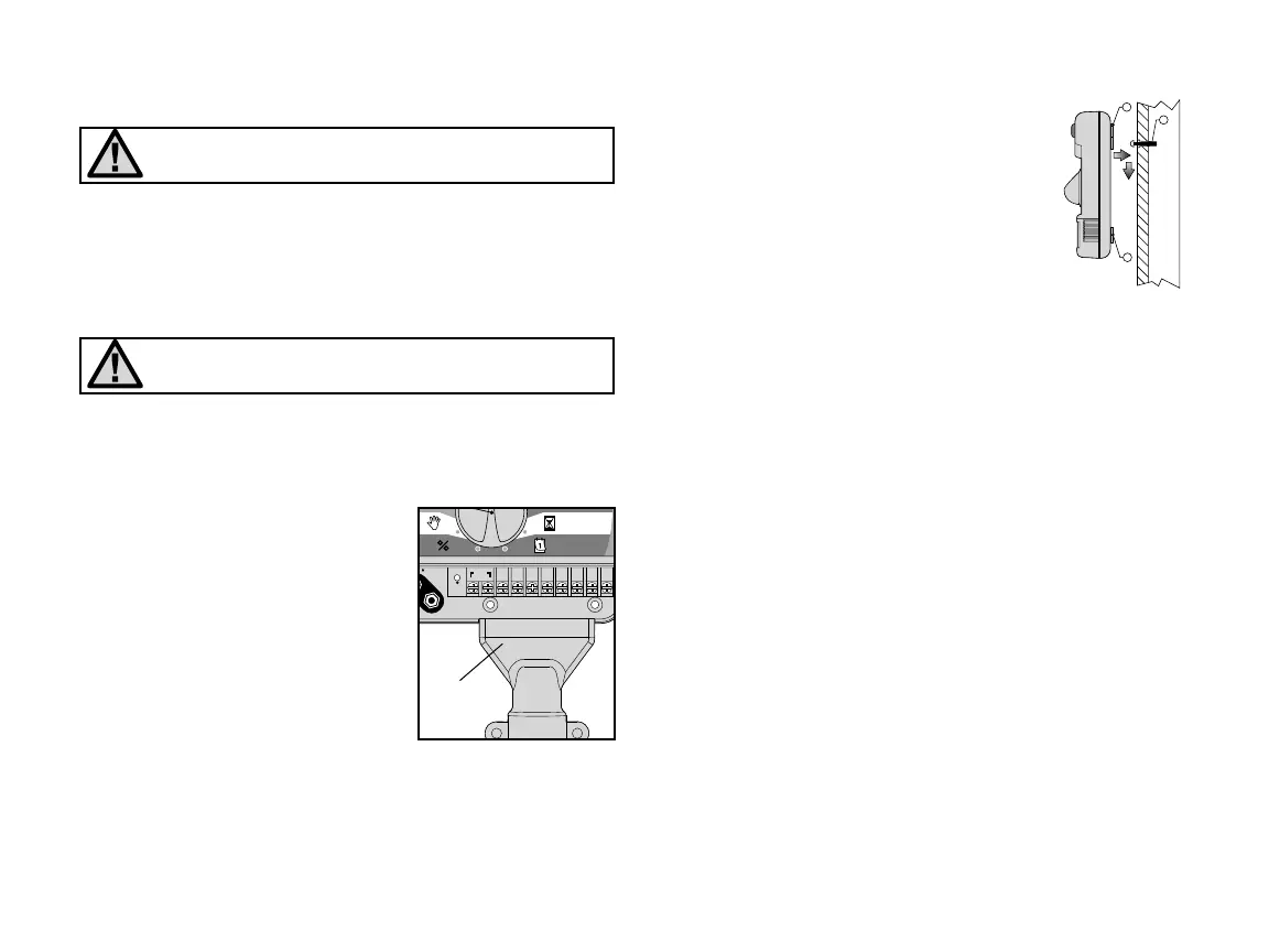
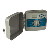
MOUNTING THE CONTROLLER TO WALL
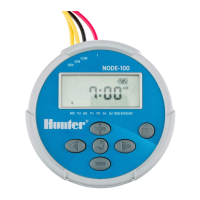
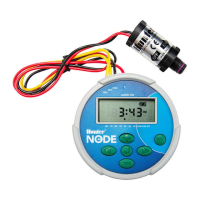
NOTE: The indoor EC is not water or weather resistant,
and must be installed indoors or in a protected area.
1. Secure one 25 mm screw (A) into the wall. Note: Install screw
anchors if attaching to drywall or masonry wall.
2. Slide the keyhole (B) on top of the controller over the screw.
3. Secure controller in place by installing screws in the holes (C)
below the terminal strip area.
Do not plug transformer into power source until the con-
troller is mounted and all valves have been connected.
Installing the Conduit Cover
(For indoor controller installations)
The conduit cover is provided to cover the field wires as they exit the
conduit into the bottom of the controller. The conduit cover can be
used with ½" or ¾" diameter conduit.
To install the Conduit Cover:
1. Remove the lower access panel
on the EC.
2. Slide the conduit cover on the
bottom edge of the controller.
3. Bring the conduit and field wires to the bottom
of the controller. Make sure that there is a
sufficient length of conduit so it enters the
conduit cover. There are two small notches on
the left side of the cover to route the 24VAC
wires from the external transformer, or wires
from the sensor and P/MV (if applicable).
4. Secure the conduit cover to the wall with the
screws and anchors provided.
5. Replace the lower access panel on the EC.
CONNECTING VALVES AND TRANSFORMER
1. Route control wires between valve location and controller. Typi-
cally it is recommended that at least 1 mm diameter conductor
cable be used.
2. At the valves, attach the common wire to either solenoid wire of
the valve. This is most commonly a white colored wire. Attach a
separate control wire to the remaining solenoid wire and make a
note of the color corresponding to each valve and the watering
station it controls.
3. Secure the wires with a waterproof wire connector to protect the
connection.
4. Secure the white valve common wire to the screw on the terminal
marked C. Connect the color-coded wires from the valves to their
appropriate station numbers and tighten the screws.
Conduit
Cover
3