21 22
Learn more. Visit hunterindustries.com/golf
TABLE OF CONTENTS I RISER SEAL REPLACEMENT
RISER SEAL REPLACEMENT I TABLE OF CONTENTS
Slide the new face-seal down and onto the riser.
Make sure that it is pressed all the way until it
is seated rmly against the ledge at the base
of the stainless-steel portion of the riser. Install
the retraction spring and seal-block assembly
onto the G80 riser. Press down on the seal-block
to compress the retraction spring and hold
rmly in this position.
To install the nozzle housing’s shroud/logo-cap
assembly, position it over the nozzle housing.
The single opening for the Primary long-range
nozzle in the shroud must be positioned directly
over the long-range (largest) nozzle. Press into
position and conrm all three nozzle openings
are lined up with the nozzles inside. Install the
stainless steel screw into the rubberized logo
cap by turning it clockwise until hand tight.
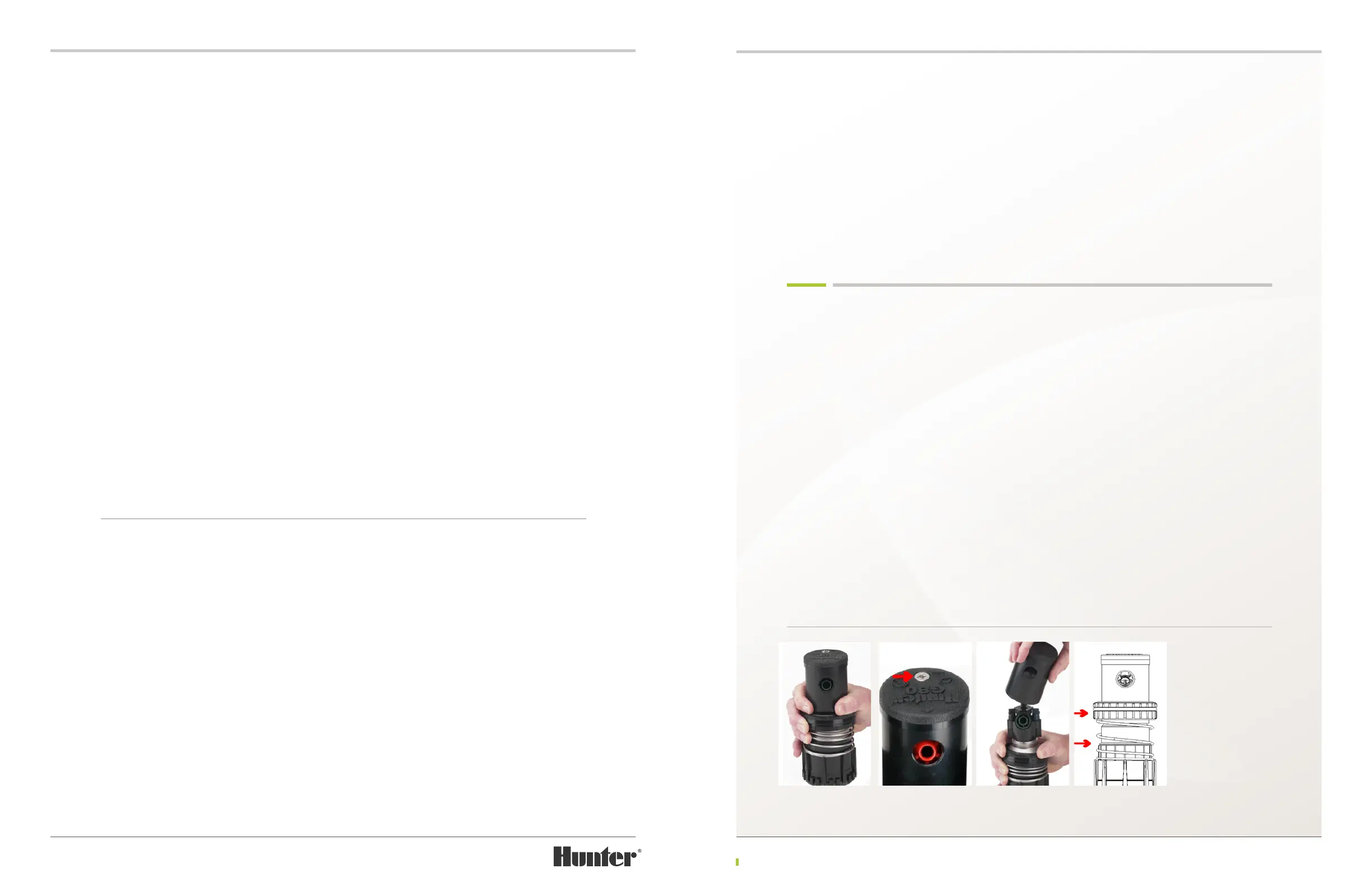
RISER SEAL REPLACEMENT G90 & G95 RISERS
The G90 and G95 riser seal assembly and the
compressed retraction spring are retained on
the riser with the retainer cap (plastic plate) at
the top of the riser assembly. It is necessary to
remove the retainer cap in order to replace the
riser seal components. To remove the retainer
cap, fully compress the riser spring by grabbing
the riser seal assembly (FIGURE 51), pressing
downward and then holding riser rmly to
prevent the spring from moving upwards.
Caution! The riser assembly is under spring tension. Eye protection should be worn and safe-
handling procedures followed when servicing this product.
Hold the riser seal assembly down with one
hand. Locate the two screws that hold the
retainer cap to the riser assembly (FIGURE
52). Use a Phillips screwdriver to engage each
retaining screw and turn counter-clockwise
to remove. Prior to removing the G90 or G95
retainer cap, note its orientation as it relates
to the nozzles below. This will help with the
assembly process later. Remove the retainer
cap and set aside.
While still holding the compressed riser seal
assembly and retraction spring with one hand,
use the other hand to grasp the bottom of the
riser assembly. Slowly release the compression
of the retraction spring until it is fully extended
and no pressure is felt. Note the orientation
of the riser components to help with assembly
later (FIGURE 53).
The riser seal on G80 risers include two primary components - the seal block assembly and the
face-seal. The seal block assembly sits on top of the retraction spring and has two sealing surfaces.
First, the seal block has an O-Ring around the outside. If the O-Ring is damaged, deteriorated or
missing, the riser will leak water while the sprinkler is operating. The second sealing surface on
the seal-block assembly is on the underside. The angled surface on the underside of the seal-block
assembly is the interface for the face-seal. If this angled interface surface is cut or otherwise
damaged, the riser can leak water during sprinkler operation.
The face-seal is the second primary component to the G80’s riser seal design. The face-seal is the
white plastic angled ring that is position at the base of the stainless-steel portion of the G80’s
riser. If the face-seal is damaged, deteriorated or missing, the riser will leak during sprinkler
operation.
If the riser is leaking during sprinkler operation, the O-Ring, the interface, and the face-seal must
be inspected in order to determine the cause of the leakage. If the O-Ring is damaged, it can
easily be replaced by removing the damaged O-Ring from the seal-block and replacing it with a
new
one. Use care to ensure that the O-Ring is not cut or twisted during the installation process. If the
interface is damaged, the entire seal-block must be replaced. Also, if the interface is damaged it
is highly likely that the face-seal is damaged as well and needs replacement.
To replace the face-seal, slide it upwards and o the riser assembly. Replacement face-seals must
t very snug to the stainless-steel on the riser. As a result, there may be considerable resistance
when attempting to install the new face-seal. To make installation easier, the face-seal’s diameter
can be expanded by placing it in the sun for several minutes. Or, if the repair is being done in the
shop, placing the face-seal in warm water for several minutes will cause expansion as well.
FIGURE 47 FIGURE 48 FIGURE 49 FIGURE 50