13 14
Learn more. Visit hunterindustries.com/golf
TABLE OF CONTENTS I NOZZLE REPLACEMENT
NOZZLE REPLACEMENT I TABLE OF CONTENTS
NOZZLE REPLACEMENT G35 & G75 RISERS
To view and replace the nozzles, it is necessary to
compress the riser spring by grabbing the riser
seal assembly (FIGURE 27), pressing downward
and then holding riser rmly to prevent the
spring from moving upwards.
The G35 nozzles are yellow with single orices.
The G75 nozzles are color-coded with two
orices. All nozzles are retained in the nozzle
housing (turret) with a setscrew (FIGURE 30).
Each setscrew has a
3
/
32
inch Allen wrench
recess at the top.
On the G35 or G75 rubberized logo cap, locate
the arrowhead shaped area directly above the
nozzle (FIGURE 31). Insert the metal end of
the Hunter wrench or a
3
/
32
inch wrench into
the membrane within the arrow that is directly
above the nozzle to be replaced. Engage the
setscrew and turn counter-clockwise until the
bottom of the setscrew clears the top of
the nozzle.
Note the nozzle’s orientation prior to removal
to aid in the nozzle installation process. Using
needle-nose pliers, grab the right side of the
nozzle on its outer ring and pull outward to
remove the nozzle. In some cases it may be
necessary to grab the nozzle’s orice to remove
the nozzle. Discard the old nozzle, as the removal
process can damage the nozzle and negatively
aect its performance.
Insert the replacement nozzle into the nozzle
housing with the smaller orice positioned to
the right. Press rmly until it stops. Turn the
nozzle-retaining setscrew clockwise while
making sure that the setscrew does not distort
the nozzle. Lower the setscrew in front of the
nozzle only as far as necessary to prevent
nozzle movement. Take care not to position the
setscrew in front of or against the nozzle’s
orice as its performance can be negatively
aected.
If the nozzle size or color has been changed,
please note that the adjustable stator will likely
need to be reset. Refer to the Stator Adjustment
section in this manual for information on how to
reset the stator.
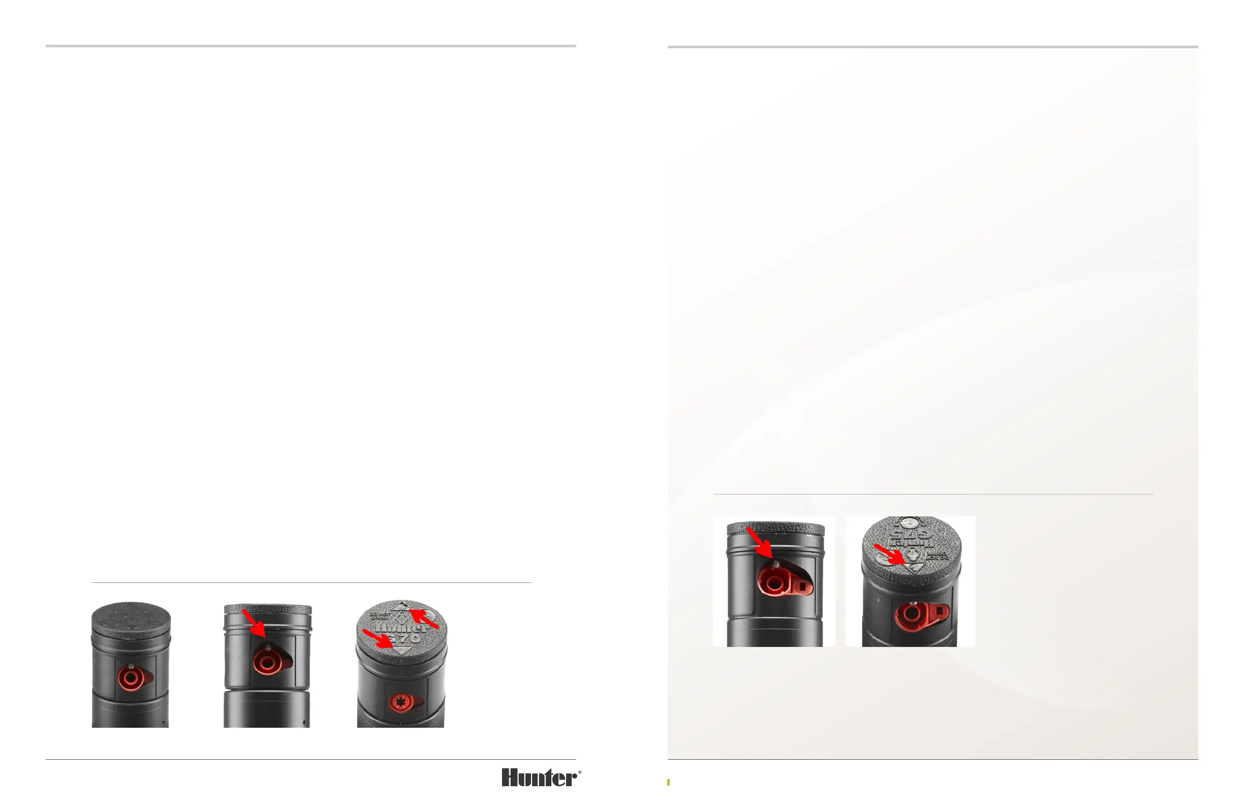
NOZZLE REPLACEMENT G70 RISERS
To view and replace the nozzles, it is necessary to follow these steps: With riser held in hand,
compress the riser spring by grabbing the riser seal assembly (FIGURE 27), pressing downward and
then hold riser rmly to prevent the spring from moving upwards.
Note: Riser assembly must be removed to change nozzles. This is necessary since stator setting
must also be adjusted when changing nozzles. See section titled, “Stator Adjustments – Why and
When Are They Needed.”
The G70 riser has two color-coded opposing nozzles. All G70 nozzles are retained in the nozzle
housing (turret) with setscrews (FIGURE 28). Each setscrew has a
3
/
32
inch Allen wrench recess
at the top. When replacing both G70 nozzles, it is important to note that the nozzles must be the
same color. These color-coded sets oer the optimum eciency for each ow range.
On the G70’s rubberized logo cap, locate the two opposing arrowhead shaped areas directly above
the nozzles (FIGURE 29). Insert the metal end of the Hunter wrench or a
3
/
32
inch wrench into the
membrane within the arrow that is directly above the nozzle to be replaced. Engage the setscrew
and turn counter-clockwise until the bottom of the setscrew clears the top of the nozzle.
Note the nozzle’s orientation prior to removal to aid in the nozzle installation process. Using
needle-nose pliers, grab the right side of the nozzle on its outer ring and pull outward to remove
the nozzle. In some cases it may be necessary to grab the nozzle’s orice to remove the nozzle.
Discard the old nozzle, as the removal process can damage the nozzle and negatively aect its
performance.
Insert the replacement nozzle into the nozzle housing with the tab positioned to the right. Press
rmly until it stops. Turn the nozzle-retaining setscrew clockwise while making sure that the
setscrew does not distort the nozzle. Lower the setscrew in front of the nozzle only as far as
necessary to prevent nozzle movement. Take care not to position the setscrew in front of or
against the nozzle’s orice as performance can be negatively aected.
If the nozzle size or color has been changed, please note that the adjustable stator will likely need
to be reset. Refer to the Stator Adjustment section for information on how to reset the stator.
FIGURE 27 FIGURE 28 FIGURE 29
FIGURE 30 FIGURE 31