7 8
TABLE OF CONTENTS I RISER SERVICING AND ADJUSTMENTS
Learn more. Visit hunterindustries.com/golf
TUBING CONNECTIONS I TABLE OF CONTENTS
CONTROL TUBING CONNECTIONS
C.O.M. Models Converted to Hydraulic Conguration
In hydraulic installations, the ange compartment should be used to make the Control Tubing
connections to the rotor. This allows for tubing connections, pressure tests and ushing of the
control lines - all without digging.
Converting C.O.M. models to the Hydraulic conguration – Remove the two stainless steel
screws and li the ange compartment lid to expose the ange compartment. Find the end of the
⅛ inch tubing that comes into the ange compartment from the bottom of the rotor (FIGURE 4).
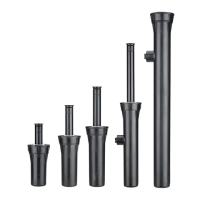
Check-O-Matic (“C”) versions of TTS rotors can be converted for use in Normally Open Hydraulic
systems by removing the end cap on the ⅛ inch tubing. To do so, slide the ¼ inch tube retainer
towards the end of the tube (FIGURE 5). Then, pull to remove the end cap with attached ¼ inch
tube retainer from the brass connector tting (FIGURE 6).
To connect the ¼ inch control tube from the controller to the TTS rotor tubing, insert ¼ inch tubing
from controller into the bottom of the ange compartment. Next, slide the ¼ inch tube retainer
(from end cap supplied with rotor) onto the ¼ inch Control Tubing. Then connect the ¼ inch
Control Tubing to the rotor’s ⅛ inch Control Tubing by pressing together at the brass tting.
Finally, slide the ¼ inch tube retainer towards the brass tting to lock the tube in place.
FIGURE 4
FIGURE 7
FIGURE 5
FIGURE 8
FIGURE 6
FIGURE 9
RISER SERVICING AND ADJUSTMENTS
CAUTION! The riser assembly is under spring tension. Eye protection should be worn and
safe-handling procedures followed when servicing this product.
TOOLS NEEDED VARIES WITH RISER MODEL
4
T-Handle Tool – PN 053191
4
Hunter Wrench – PN 172000
4
Snap-ring Tool – PN 052510
4
Needle-Nose Pliers
4
Flat Blade Screwdriver
4
Phillips Screwdriver
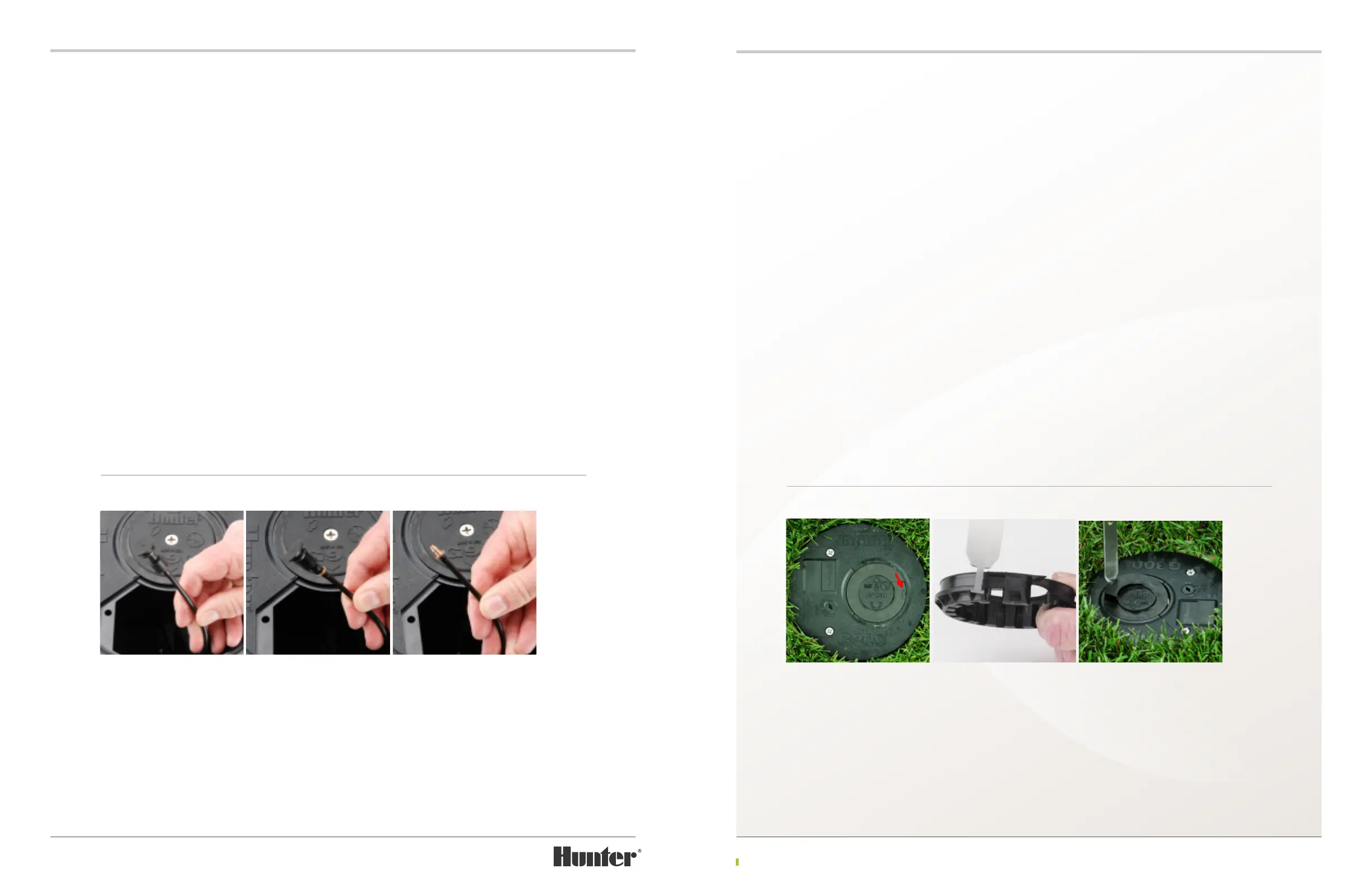
UPPER SNAPRING REMOVAL G800 SERIES
Hold Snap-ring Tool vertical over the rotor’s
upper snap ring. Align the metal end of the
snap-ring tool to the indicator on the snap-ring’s
rubberized wiper seal (FIGURE 7). Use the palm
of the other hand to drive the tool downward &
through the rubberized membrane. Tool should
penetrate about ½ inch into the snap-ring
assembly (FIGURE 8). While holding the tool
within the snap-ring, press the tool’s handle
downward and away from the center of the rotor.
As the tool is pressed downward, the snap-ring
will li from the rotor (FIGURE 9). While using
the tool to hold the snap-ring in this elevated
position, use the other hand to pull the snap-
ring from the rotor. If the snap-ring’s rubberized
wiper seal appears to be the only part that is
liing, the tool has not penetrated into the
snap-ring far enough.