37 38
Learn more. Visit hunterindustries.com/golf
TABLE OF CONTENTS I INLET VALVE SERVICING
INLET VALVE REMOVAL I TABLE OF CONTENTS
INLET VALVE SERVICING ALL MODELS
Inlet Valves (also commonly known as foot
valves) do not have serviceable internal parts
and the valves are welded together as an
assembly. As a result, inlet valves cannot be
taken apart. Any disassembly of an inlet valve
will lead to a valve that is no longer usable.
Contamination within the inlet valve can cause
the valve to leak. To remove contamination
within the inlet valve, follow the procedures
below:
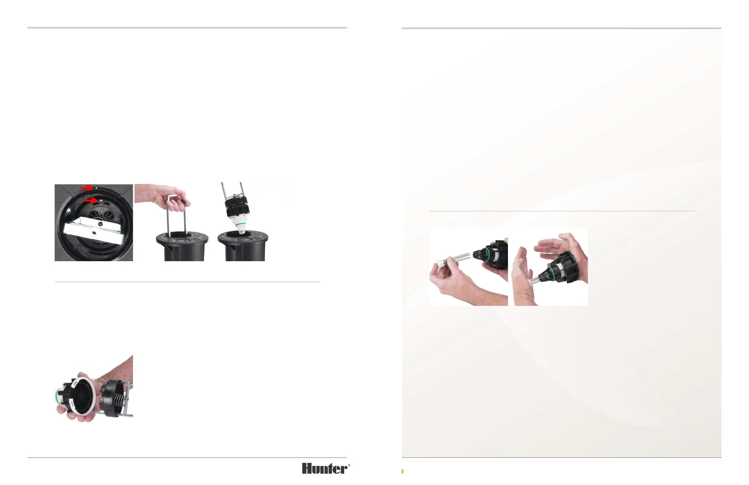
Fill a bucket with clean water. Using the TTS
Valve Flushing Tool, insert the stainless steel
metal pins on the tool into the holes at the
bottom of the inlet valve’s screen (FIGURE
98). While holding the TTS Valve Flushing Tool
in the palm of one hand and the top of the
inlet valve with the other hand, lower the inlet
valve into the bucket of water. To clean & ush
contamination from the valve, rmly push the
tool into the valve (FIGURE 99). Resistance
will be felt as the valve’s internal spring is
compressed. Cycle the valve open & closed
with the tool multiple times while holding it
submerged in the bucket of water. Remove
the valve from the water and inspect for any
remaining contamination.
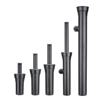
To remove the inlet valve, it is necessary to align the pointer arrow on the G900 Valve Tool with
the alignment dot on the rotor’s ange. The alignment dot is centered on the ange compartment
lid adjacent to (next to) the body cavity opening. A second alignment dot is located below the lid
in case the ange compartment lid has been removed. Align the pointer arrow on the tool with the
alignment dot (FIGURE 94) and lower the tool into the rotor’s body (FIGURE 95).
As the G900 Valve Tool is lowered into the rotor’s body, recessed areas on the black plastic part
on the tool will engage vertical rails inside the body wall. The tool must engage these rails or the
tool will not align with the inlet valve below. Continue pressing downward compressing the spring
on the G900 Valve Tool. While holding the tool down with the spring compressed, turn the tool’s
handle clockwise until it stops. Next, release the spring’s compression by liing the handle slightly
on the G900 Valve Tool. This action hooks and locks the inlet valve to the tool. Finally, pull upward
on the tool’s handle to remove the tool and inlet valve from the rotor’s body (FIGURE 96).
FIGURE 94 FIGURE 95 FIGURE 96
Important – Take note of how the G900 Valve Tool nests with the attached inlet valve. This will
help later when attaching the inlet valve to the tool prior to inlet valve installation.
To disengage the inlet valve from the G900 Valve Tool, hold the inlet valve with one hand and the
tool with the other hand. Next, push the tool’s handle toward the inlet valve to compress the tool’s
spring. With the spring held compressed, rotate the tool’s handle counter-clockwise to release the
tool’s hooks from the inlet valve.
FIGURE 97
FIGURE 98 FIGURE 99
rotate the tool’s handle counter-clockwise to re-
lease the tool’s hooks from the inlet valve.