55 56
Learn more. Visit hunterindustries.com/golf
TABLE OF CONTENTS I PRESSURE REGULATOR ADJUSTMENT
ATTACHING SELECTOR CAP TO SOLENOID I TABLE OF CONTENTS
ATTACHING SELECTOR CAP TO THE SOLENOID
The Selector Cap turns the Solenoid when the user changes the ON-AUTO-OFF settings. Under
normal operating conditions, the Selector Cap should not need replacement. The Selector Cap can
become damaged if the incorrect tool is used to make ON-AUTO-OFF selection adjustments.
With the Solenoid and Pilot Valve assembly installed in the ange compartment and the Solenoid
set to the Auto position (see instructions above), proceed as follows. The at side of the Solenoid
should be facing away from the rotor’s riser assembly pointing towards the outside of the ange
compartment (FIGURE 142).
Starting from where the Solenoid’s lead wires come out of the top of the Solenoid, place the lead
wires side-by-side over the top and down the at side of the Solenoid (FIGURE 143). While holding
the Solenoid’s lead wires in this position, place the Selector Cap on top of the Solenoid. The
Selector Cap must be oriented such that the Solenoid’s lead wires t into the recessed channel
on the inside wall of the Selector Cap. Press the Selector Cap down and onto the Solenoid
(FIGURE 144).
PRESSURE REGULATOR PURPOSE, SETTINGS AND ADJUSTMENT PROCEDURES
Regulation settings are preset at the factory. If the installed rotor has been preset to the specied
regulation setting for your irrigation system, further Pressure Regulator adjustments are not
normally necessary. If a replacement TTS rotor is being installed, it may be necessary to adjust the
regulation setting.
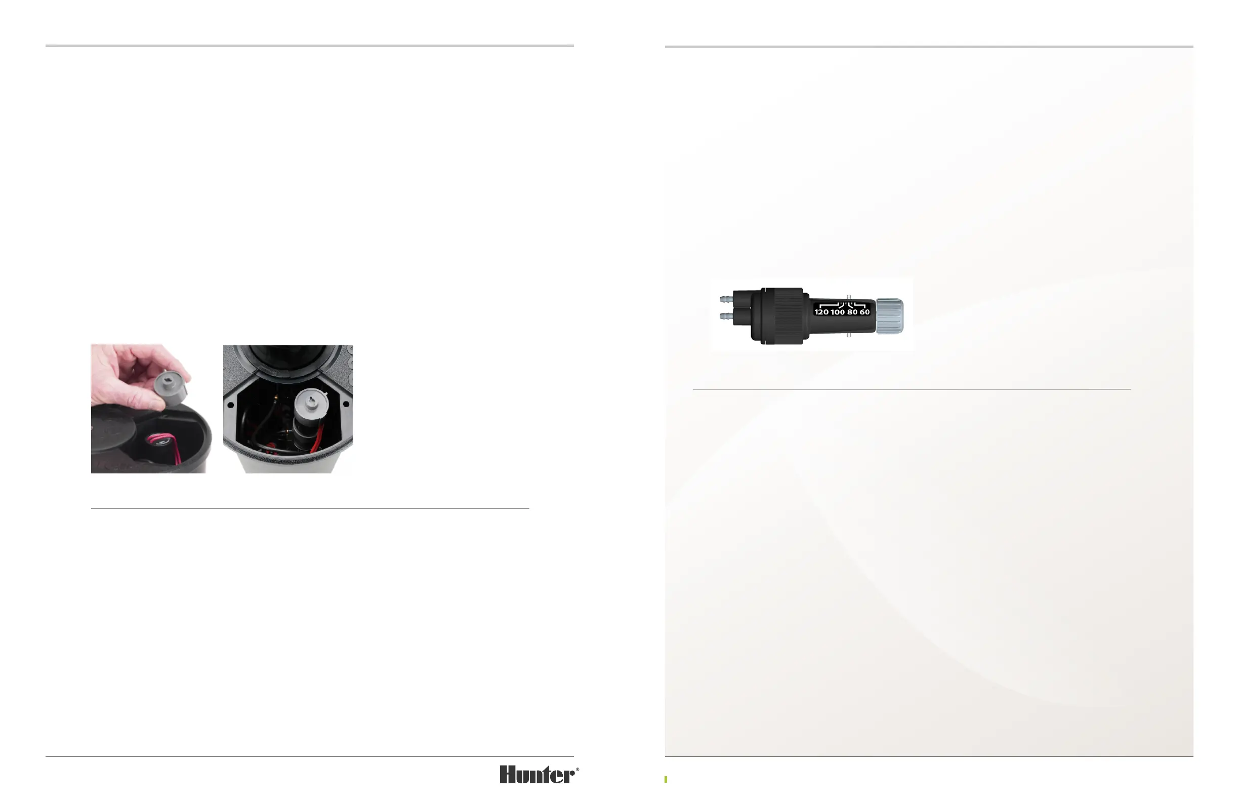
Pressure Regulator Purpose – The purpose of the Pressure Regulator (FIGURE 145) is to ensure
that a specically set pressure is supplied to the rotor’s nozzles. Since the amount of ow through
the nozzles is aected by pressure, supplying a consistent pressure to every rotor in the irrigation
system is benecial. This will help to ensure that all rotors with the same size nozzles will have the
same application rate (also known as the precipitation rate).
Pressure regulation also prevents too much
pressure from reaching the nozzles. Rotors
that are closer to the pump station or rotors
that are at a lower elevation will have relatively
higher pressures than rotors that are at the
far reaches of the irrigation system’s piping or
those at higher elevations. Abnormally high
pressures at the nozzles can cause misting of
the water droplets. Water that is misting will
be easily carried away from its intended target
by the wind.
Pressure Regulator Settings – All electric
valve-in-head TTS rotors have adjustable Pressure
Regulators. One of the many benecial features
of the TTS rotor is the fact that the Pressure
Regulation is conveniently adjustable yet hidden
within the ange compartment. This prevents
untrained personnel or golfers from shutting
down a rotor during operation and inadvertently
changing its regulation setting.
PRESSURE REGULATOR ADJUSTMENT
The variable setting Pressure Regulator has
been calibrated from the factory and set to a
specic regulation setting. This setting will not
normally need to be changed. The variable
Pressure Regulator has a pointer and a pressure
indicating scale on the side of its body with a
range of 60 PSI to 120 PSI. If pressure setting
adjustments are required, it is important to note
the following:
The calibrated pressure setting from the
factory is very accurate. However, the pressure
indicating scale is only a pressure setting
reference when making adjustments in the
eld. For more precise pressure regulation
adjustment in the eld, use a pitot gauge at the
nozzle to the check pressure.
FIGURE 143 FIGURE 144
FIGURE 145