5 6
Learn more. Visit hunterindustries.com/golf
TABLE OF CONTENTS I 0NAUTOOFF SELECTION
SOLENOID CONNECTIONS I TABLE OF CONTENTS
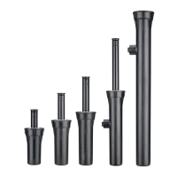
SOLENOID CONNECTIONS
Electric VIH Models
TTS Electric Valve-In-Head models have
solenoid lead wires protruding from the rotor’s
body in the traditional manner. Controller eld
wires can be connected to the rotor, using the
specied watertight wiring connectors, at this
sub-surface position. If specied or requested
otherwise, the solenoid lead wires and controller
eld wires can be pulled up into the rotor’s
ange compartment where the initial
connections can be made (recommended).
Regardless of the initial connection point, future
solenoid repair connections can be made within
the ange compartment (see Solenoid Servicing
later in this manual).
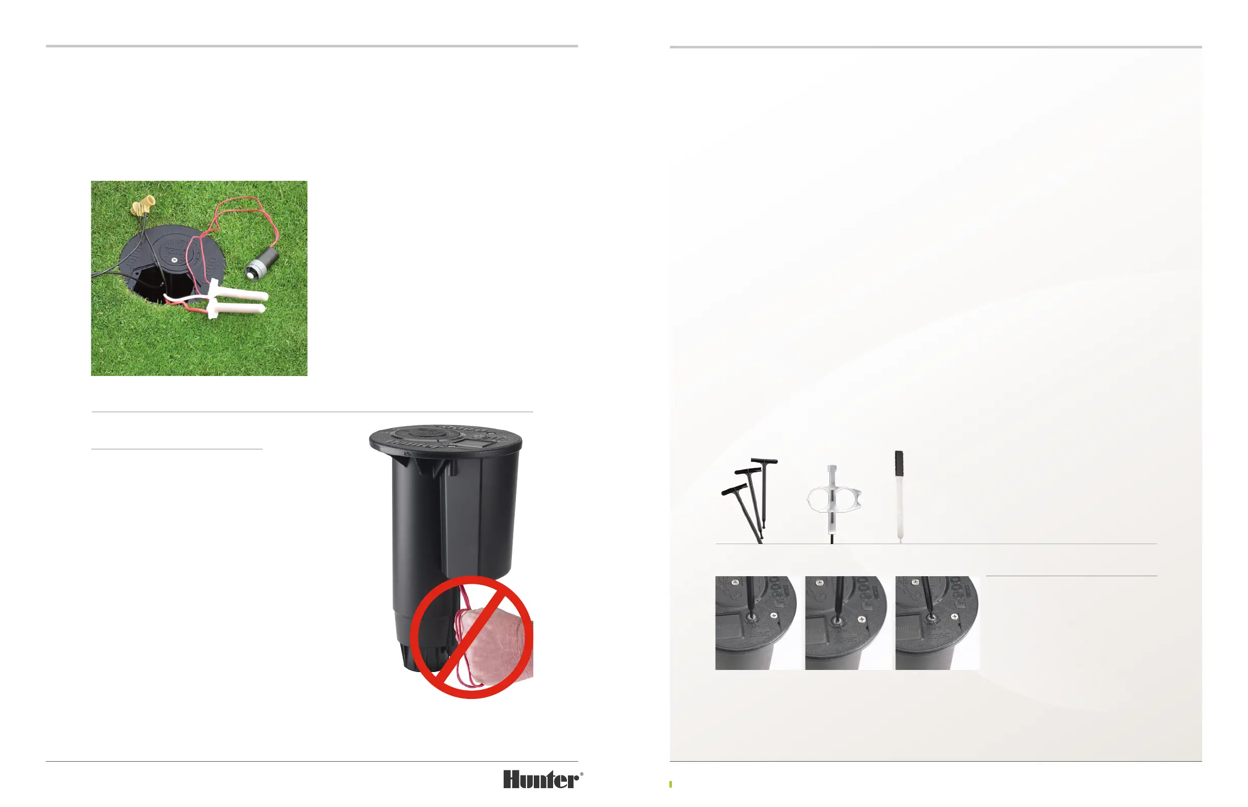
ON-AUTO-OFF SELECTION
Electric VIH Models
Electric Valve-In-Head TTS rotors are equipped
with a selector to control operation of the rotor.
The selector is located on the ange compart-
ment’s lid. From the factory, the selector is set
to the AUTO position which is located midway
between the ON and OFF positions (FIGURE 1).
Several tools are available to make ON-AUTO-OFF selections:
4
T-Handle Tool – PN 053191
4
Hunter Wrench – PN 172000
4
Snap-ring Tool – PN 052510
The ON-AUTO-OFF selector’s function and
recommended operation is as follows:
AUTO – The selector comes from the factory
in the AUTO position. When in this position,
the rotor will not activate unless the controller
sends 24 volts of power to the rotor’s solenoid
(FIGURE 1).
OFF – Using one of the tools listed above, turn
the selector approximately ¼ turn clockwise
from the AUTO position to manually deactivate
the rotor. In the OFF position, (FIGURE 2) the
rotor will not activate even if the controller
sends 24 volts of power to the rotor’s solenoid. To
restore activation by the controller’s programming,
return the selector to the AUTO position.
ON – Using one of the tools listed above, turn
the selector ¼ turn counter-clockwise from the
AUTO position to manually activate the rotor
(FIGURE 3). The rotor will continue to operate
until the selector is returned to the AUTO or O
position. De-activation of the sprinkler may take
several seconds.
CAUTION! When connecting
solenoid leads outside of the ange
compartment, DO NOT pull solenoid
leads downward in an attempt to
provide more exposed solenoid
wire. Electric TTS rotors REQUIRE
slack in solenoid wiring within the
ange compartment to facilitate
servicing of the pilot valve and
solenoid. Removing the slack can
limit movement of the On-Auto-
O selector and require cutting of
solenoid wires to service pilot valve
and/or solenoid.
FIGURE 1 FIGURE 2 FIGURE 3
CAUTION! Do not over-tighten
the selector when turning to the
manual OFF position. Turn only until
resistance is felt. Over-tightening
can cause premature failure of the
solenoid’s plunger seal and lead to
the rotor leaking water in the
AUTO position.
Do NOT Pull On
Solenoid Lead
Wiring