53 54
Learn more. Visit hunterindustries.com/golf
TABLE OF CONTENTS I ATTACHING SOLENOID ASSEMBLY
CONNECTING SOLENOID TO PILOT VALVE I TABLE OF CONTENTS
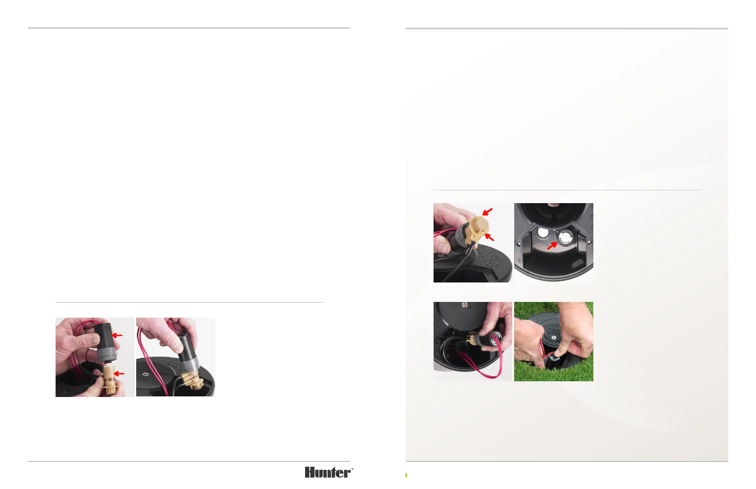
ATTACHING THE ASSEMBLED SOLENOID AND PILOT VALVE
TO THE FLANGE COMPARTMENT
With the Solenoid and Pilot Valve correctly
assembled as outlined above, look at the
bottom of the Pilot Valve. Notice there are two
opposing sections of plastic that protrude to the
outside and away from the center (FIGURE 139).
These two “ears” must engage the Pilot Valve’s
mounting base in the body ange compartment
during installation (FIGURE 140).
To install the Solenoid and Pilot Valve, rst
position yourself to the side of the rotor such
that the rotor’s ange compartment is at the
6:00 position (closest to you). Next, lower the
Solenoid and Pilot Valve assembly (FIGURE 141)
into the ange compartment with the Pilot
Valve’s ttings pointing to the le side (9:00
position). Engage the bottom of the Pilot Valve
with the Pilot’s Valve’s mounting base located
at the right and rear of the ange compartment.
Press down to engage Pilot Valve’s mounting
ears (FIGURE 142).
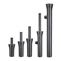
CONNECTING SOLENOID TO THE PILOT VALVE
To ensure that the On-O-Auto feature functions properly, follow the procedure outlined below.
The TTS rotor’s Solenoid has double-lead threads. If this procedure is not followed, the Solenoid
can be attached to the Pilot Valve 180 degrees out of position. While the On-O-Auto feature will
function if connected out of position, it will function much better if connected correctly.
First, notice that there is a at section on one side of the Solenoid (FIGURE 137). This “at” is used
as a reference when connecting the Solenoid to the Pilot Valve. Next, notice there is also a at
section along the side of the Pilot Valve at a point opposite of the upper tting. This “at” is the
second reference when connecting the Solenoid to the Pilot Valve.
With the gray Detent Ring attached to the bottom of the Solenoid, bring the Solenoid and the
Pilot Valve together. Prior to engaging the Solenoid and Pilot Valve threads, align the ats on the
Solenoid and Pilot Valve then press together. Prior to turning Solenoid clockwise, you must rst
turn the Solenoid counter-clockwise ⅛ of a turn. This action ensures that the correct rst thread
on Solenoid engages the rst thread on the Pilot Valve. Now press the Solenoid & Pilot Valve
together while threading the Solenoid clockwise onto the Pilot Valve.
Next, the Solenoid must be placed in the Auto position. To do so, keep turning the Solenoid
clockwise onto the Pilot Valve until it stops (bottoms out). Do not tighten! Then, turn the Solenoid
counter-clockwise until you feel the rst Detent Ring click (FIGURE 138). This is the Auto position.
To check for proper alignment, position the connected Solenoid and Pilot Valve assembly in your
hand so you are looking at the top. Next, rotate the Solenoid and Pilot Valve assembly until the
“at” on the Solenoid is at the 12:00 position (do not unthread Solenoid from Pilot Valve). With the
Solenoid’s at in the 12:00 position, the Pilot valve’s ttings should be at the 3:00 position. If the
ttings are not at the 3:00 position, disconnect and repeat the procedure.
FIGURE 137 FIGURE 138
FIGURE 139
FIGURE 141
FIGURE 140
FIGURE 142