17 18
Learn more. Visit hunterindustries.com/golf
TABLE OF CONTENTS I NOZZLE REPLACEMENT
NOZZLE REPLACEMENT I TABLE OF CONTENTS
To remove the long-range primary nozzle, rst note the nozzle’s orientation prior to removal.
The G90’s primary nozzle has a protruding rail that must engage the slot on the right side of the
nozzle opening. Understanding this will help during the installation process later. Using needle-
nose pliers, grab the nozzle’s outer ring next to the recess on the right side of the nozzle opening
and then pull outward. If necessary, grab the nozzle’s orice to gain a better grip. Discard the old
nozzle as the removal process can damage the nozzle and negatively aect the performance.
Insert the replacement nozzle into the nozzle housing. Press rmly until the nozzle stops. Turn
the nozzle-retaining setscrew clockwise while making sure that the setscrew does not distort
the nozzle. Lower the setscrew in front of the nozzle only as far as necessary to prevent nozzle
movement. Take care not to position the setscrew in front of or against the nozzle’s orice as
performance can be negatively aected.
If the nozzle size or color has been changed, please note that the adjustable stator will likely need
to be reset. Refer to the Stator Adjustment section in this manual for information on how to reset
the stator.
The G90’s short-range and mid-range nozzles are performance matched to all G90 long-range
nozzles. As a result, replacement of these nozzles is normally required only when a nozzle has
been damaged. If replacement does become necessary, it is important to note that these nozzles
must be installed in the correct orientation for optimal performance.
Prior to removal of the G90’s short-range or mid-range nozzle, note the dierences between the
nozzle on the le and right.
G90 Full Circle: The short-range nozzle is black and on the le side date codes 0511 &
prior (FIGURE 39).
The short-range nozzle is red and on the le dates codes
0611 and aer. (FIGURE 39).
The mid-range nozzle is blue and on the right side (FIGURE 39).
Using needle-nose pliers, grab the nozzle’s orice then pull outward. Discard the old nozzle
as the removal process will damage the nozzle and negatively aect the performance. Insert
the replacement nozzle into the nozzle housing and press rmly until it stops. Turn the nozzle-
retaining setscrew clockwise to a position in front of the nozzle that prevents nozzle movement.
Take care not to position the setscrew in front of or against the nozzle’s orice as its performance
can be negatively aected.
NOZZLE REPLACEMENT G95 RISERS
To view and replace the nozzles, it is necessary to compress the riser spring by grabbing the riser
seal assembly (FIGURE 37), pressing downward and then holding riser rmly to prevent the spring
from moving upwards.
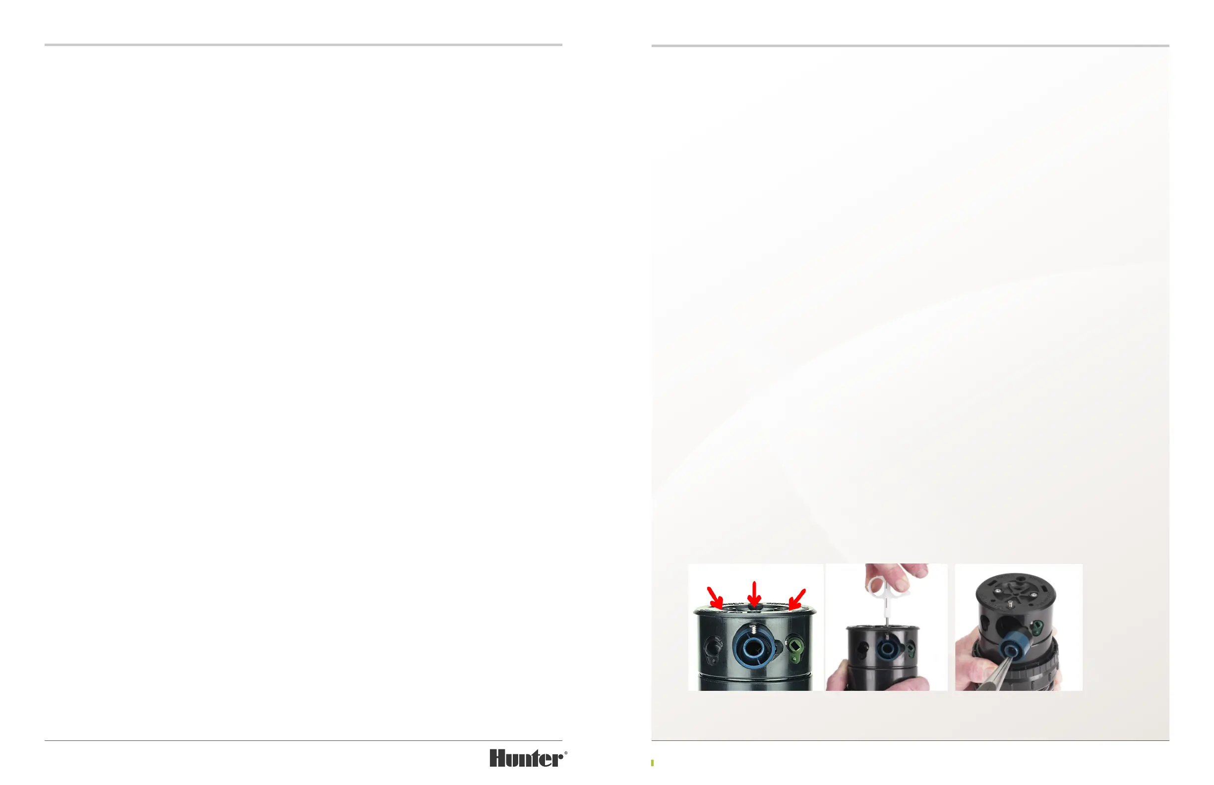
The G95 riser has three color-coded nozzles
that all face the same direction. All G95 nozzles
are retained in the nozzle housing (turret) with
three setscrews (FIGURE 40). Each setscrew
has a
3
/
32
inch Allen recess at the top. Insert
the metal end of the Hunter wrench or a
3
/
32
inch wrench into setscrew that is above the
nozzle to be replaced. Engage the setscrew and
turn counter-clockwise until the bottom of the
setscrew clears the top of the nozzle (FIGURE 41).
To remove the long-range primary nozzle, rst
note the nozzle’s orientation prior to removal.
The G95’s primary nozzle has a protruding rail
that must engage the slot on the right side of
the nozzle opening. Understanding this will
help during the installation process later.
Using needle-nose pliers, grab the nozzle’s
outer ring next to the recess on the right side
of the nozzle opening and then pull outward
(FIGURE 42). If necessary, grab the nozzle’s
orice to gain a better grip. Discard the old
nozzle as the removal process can damage the
nozzle and negatively aect its performance.
Insert the replacement nozzle into the nozzle
housing. Press rmly until the nozzle stops.
Turn the nozzle-retaining setscrew clockwise
while making sure that the setscrew does not
distort the nozzle. Lower the setscrew in front
of the nozzle only as far as necessary to prevent
nozzle movement. Take care not to position the
setscrew in front of or against the nozzle’s orice
as its performance can be negatively aected.
If the nozzle size or color has been changed,
please note that the adjustable stator will likely
need to be reset. Refer to the Stator Adjustment
section in this manual for information on how to
reset the stator.
The G95’s short-range and mid-range nozzles
are performance matched to all G95 long-range
nozzles. As a result, replacement of these nozzles
is normally required only when a nozzle has
been damaged. If replacement does become
necessary, it is important to note that these
nozzles must be installed in the correct
orientation for optimal performance.
Prior to removal of the G95’s short-range or
mid-range nozzle, note the dierences between
the nozzle on the le and right.
G95 Adj. Arc: The short-range nozzle is black and on the le side date codes 0511 and
prior (FIGURE 40).
The short-range nozzle is red and on the le side date codes 0611 and aer
The mid-range nozzle is green and on the right side (FIGURE 40).
FIGURE 40 FIGURE 41 FIGURE 42