15 16
Learn more. Visit hunterindustries.com/golf
TABLE OF CONTENTS I NOZZLE REPLACEMENT
NOZZLE REPLACEMENT I TABLE OF CONTENTS
NOZZLE REPLACEMENT G80 RISERS
To view and replace the nozzles, it is necessary to compress the riser spring by grabbing the riser
seal assembly (FIGURE 32), pressing downward and then holding riser rmly to prevent the spring
from moving upwards.
The G80 riser has three color-coded opposing nozzles. All G80 nozzles are retained in the nozzle
housing by the shroud (FIGURE 33) that covers the nozzle housing (turret). To remove the shroud,
use a Phillips head screwdriver and remove the stainless steel screw at the top of the riser by
turning it counter-clockwise. Prior to removal of the shroud, take note that the large nozzle arrow
on top of the shroud’s rubberized logo cap is orientated directly over the larger, long-range nozzle
(FIGURE 34). This will help with the shroud installation process later.
While rmly holding the compressed spring and seal assembly downward, grab and li the shroud
o the nozzle housing (FIGURE 35). If preferred, slowly li and release the compressed spring
and seal assembly then remove them from the riser assembly. Note the orientation of the seal
assembly for installation later. Or alternatively, continue to rmly hold the compressed spring and
seal assembly downward while removing and replacing nozzles.
To remove the G80 long-range primary nozzle, use needle-nose pliers to grab the nozzle’s orice
then pull outward (FIGURE 36). Discard the old nozzle as the removal process can damage the
nozzle and negatively aect its performance. Prior to nozzle replacement, note that there is a
notch (recessed area) on the nozzle’s outer ring. Insert the replacement nozzle into the nozzle
housing with this recess positioned at the top. The correct orientation of the recessed area is
important as it is part of the G80’s nozzle retention system. Press in rmly until the nozzle stops.
The G80’s short-range and mid-range nozzles are performance matched to all G80 long-range
nozzles. As a result, replacement of these nozzles is normally required only when a nozzle has
been damaged. If replacement does become necessary, it is important to note that these nozzles
must be installed with the correct orientation for optimal performance.
Prior to removal of the short-range or mid-
range nozzle, note the dierences between the
nozzle on the le and right. When facing the
short-range and mid-range nozzles:
G80 Full Circle: The short-range nozzle is black and on the right side.
The mid-range nozzle is blue and on the le side.
To remove the short or mid-range nozzle, grab
and rotate the nozzle 90 degrees to the outside
(away from turret) then wiggle and pull it
upward. To install a short-range or mid-range
nozzle, position the nozzle so the orice is
pointing outward and to the side. Drop the
nozzle into position by wiggling it downward.
The nal step is to rotate the nozzle 90 degrees
pointing it in the opposite direction of the
primary long-range nozzle. This action locks the
nozzle in the nozzle housing.
Prior to installation of the shroud, replace the
retraction spring and seal assembly (if removed
prior). To install the nozzle housing shroud,
position the shroud over the nozzle housing.
The single opening for the Primary long-range
nozzle in the shroud must be positioned directly
over the nozzle. Press into position and conrm
all three nozzle openings are lined up with
the nozzles inside. Install the stainless steel
screw into the rubberized logo cap by turning
it clockwise until hand tight. If the nozzle size
or color has been changed, please note that the
adjustable stator will likely need to be reset.
Refer to the Stator Adjustment section in
this manual for information on how to reset
the stator.
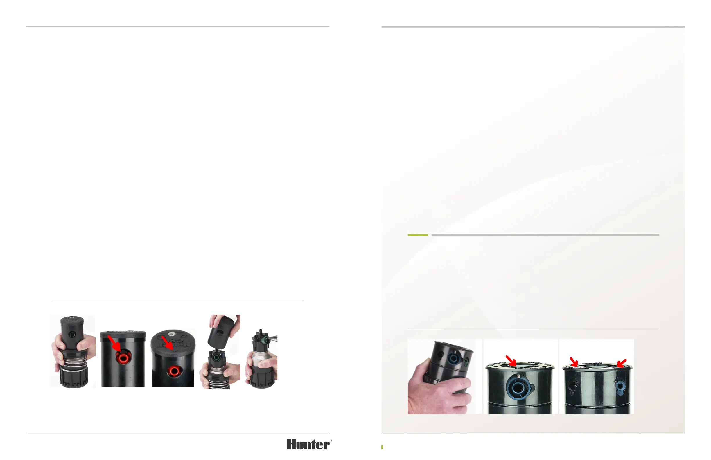
NOZZLE REPLACEMENT G90 RISERS
To view and replace the nozzles, it is necessary
to compress the riser spring by grabbing the
riser seal assembly (FIGURE 37), pressing
downward and then holding riser rmly to
prevent the spring from moving upwards.
The G90 riser has three color-coded opposing
nozzles. All G90 nozzles are retained in the
nozzle housing (turret) with three setscrews
(FIGURE 38 & 39). Each setscrew has a
3
/
32
inch
Allen recess at the top. Insert the metal end of
the Hunter wrench or a
3
/
32
inch wrench into
setscrew that is above the nozzle to be replaced.
Engage the setscrew and turn counter-
clockwise until the bottom of the setscrew
clears the top of the nozzle.
FIGURE 32 FIGURE 33 FIGURE 34 FIGURE 35 FIGURE 36
FIGURE 37 FIGURE 38 FIGURE 39