19 20
Learn more. Visit hunterindustries.com/golf
TABLE OF CONTENTS I RISER SEAL REPLACEMENT
RISER SEAL REPLACEMENT I TABLE OF CONTENTS
Using needle-nose pliers, grab the nozzle’s orice then pull outward. Discard the old nozzle as
the removal process will damage the nozzle and negatively aect the performance. Insert the
replacement nozzle into the nozzle housing and press rmly until it stops. Turn the nozzle-
retaining setscrew clockwise to a position in front of the nozzle that prevents nozzle movement.
Take care not to position the setscrew in front of or against the nozzle’s orice as its performance
can be negatively aected.
RISER SEAL REPLACEMENT G35, G70 & G75 RISERS
The G35, G70 and G75 riser seal assemblies and the compressed retraction spring are retained
on the risers with the rubberized logo cap assembly. It is necessary to remove the rubberized
logo cap assembly in order to replace the riser seal assembly. To remove the rubberized logo cap
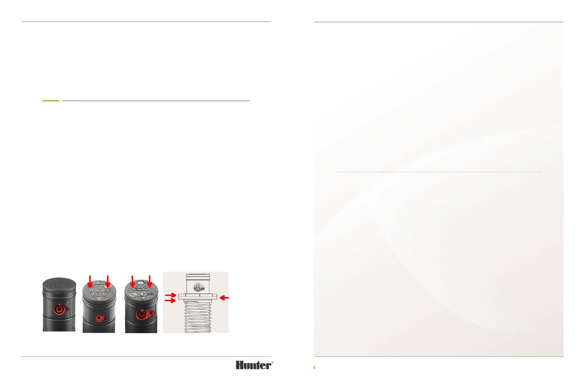
assembly, it is necessary to fully compress the riser spring by grabbing the riser seal assembly
(FIGURE 43), pressing downward and then holding riser rmly to prevent the spring from moving
upwards.
Caution! The riser assembly is under spring tension. Eye protection should be worn and safe-
handling procedures followed when servicing this product.
Hold the riser seal assembly down with one hand. Using the other hand, locate the two hidden
screws that retain the rubberized logo cap assembly. These can be found by pressing down on the
rubberized logo cap close to the “H” and the “r” on the Hunter logo (FIGURE 44 & 45). The Phillips
headed retaining screws are directly beneath these depressions. Insert the Phillips screwdriver
through the rubberized membrane and engage each retaining screw. Turn counter-clockwise to
remove each screw.
Prior to removing the rubberized logo cap assembly, note its orientation as it relates to the
nozzles below. This will help with the assembly process later. Remove the rubberized logo cap and
set aside.
While still holding the compressed riser seal
assembly and retraction spring with one hand,
use the other hand to grasp the bottom of the
riser assembly. Slowly release the compression
of the retraction spring until it is fully extended
and no pressure is felt.
Prior to removing the riser seal assembly, note
the orientation and sequence of the three
individual seal assembly parts (FIGURE 46).
The Upper Seal Support is on top and its lower
surface nests perfectly with the top of the riser
seal. The Riser Seal is the rubberized part in the
middle. The Lower Seal Support (also known as
the Upper Spring Support) has an upper surface
that nests perfectly to the lower surface of the
Riser Seal. The Support’s lower surface also
provides a nest for the retraction spring. During
assembly, these three parts must keep this
sequence and orientation in order for the seal
assembly to function properly.
If any one of the three parts in the seal assembly
needs replacement, it is highly recommended
that all three components be replaced. To
reassemble the riser, place the seal assembly
on top of the retraction spring and then compress.
While rmly holding the retraction spring and
seal assembly down, place the logo cap assembly
on top of the riser in the correct orientation.
Insert the two stainless-steel screws through
the rubberized membranes on the logo cap and
hand tighten with a Phillips screwdriver.
RISER SEAL REPLACEMENT G80 RISERS
The G80 riser seal-block assembly and the
compressed retraction spring are retained on
the riser with the shroud/logo-cap assembly. It
is necessary to remove this assembly in order
to service the G80’s riser seal components. To
remove the shroud/logo-cap assembly, it is
necessary to fully compress the riser spring by
grabbing the riser seal-block assembly, pressing
downward and then holding riser rmly to
prevent the spring from moving upwards
(FIGURE 47).
Caution! The riser assembly is under spring tension. Eye protection should be worn and safe-
handling procedures followed when servicing this product.
Press the riser seal-block assembly down with
one hand and hold rmly. Locate the stainless-
steel retaining screw on top of the shroud/
logo-cap assembly (FIGURE 48). Use a Phillips
screwdriver to engage the screw and turn
counter-clockwise to remove. Prior to removal
of the shroud, take note that the large nozzle
arrow on top of the shroud’s rubberized logo
cap is orientated directly over the larger, long-
range nozzle. This will help with the shroud
installation process later.
While rmly holding the compressed spring and
seal-block assembly downward, grab and li the
shroud o the nozzle housing then set it aside
(FIGURE 49). Slowly li to release the spring
compression. Note the orientation of the seal-
block assembly for installation later (FIGURE
50). Next, remove the seal-block assembly and
retraction spring.
FIGURE 43 FIGURE 44 FIGURE 45 FIGURE 46