29 30
Learn more. Visit hunterindustries.com/golf
TABLE OF CONTENTS I UPPER SNAPRING INSTALLATION
UPPER SNAPRING INSTALLATION I TABLE OF CONTENTS
As the rubberized logo cap is installed, note
there is a protruding pin on the underside of the
rubberized logo cap (FIGURE 70). This pin is the
alignment feature on the rubberized logo cap
that must be oriented and inserted into the
riser assembly correctly. Proper alignment and
installation of the protruding pin allows the
nozzle direction arrows on the rubberized logo
cap to be positioned over the nozzles below.
Note which hole the pin ts into (FIGURE 71).
Also note that the pin and hole locations are
dierent for the G90 and G95 rotors.
Install the rubberized logo cap using a Phillips
screwdriver. Tighten the stainless screw
clockwise until the screw is hand tight. Do not
over-tighten.
UPPER SNAPRING INSTALLATION G800 SERIES
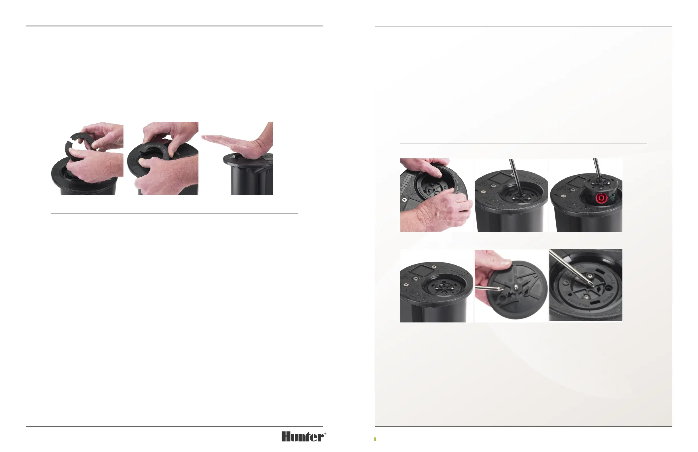
Hold the snap-ring in front of you with the wiper seal facing up and the snap-ring open ends at the
top. The snap-ring end on the le must be installed rst (FIGURE 65). Lay the snap-ring on top of
the rotor and use the le thumb to force the le open end of the snap-ring into the upper snap-
ring groove within the body (FIGURE 66). Once engaged, the remaining portion of the snap-ring
can be installed by pressing in a counter-clockwise motion around the snap-ring (FIGURE 67).
UPPER SNAPRING INSTALLATION G900 SERIES
Hold the snap-ring in front of you with the wiper seal facing up and the snap-ring open ends at
the top. The snap-ring end on the le must be installed rst. Lay the snap-ring on top of the rotor
and use the le thumb to force the le open end of the snap-ring into the upper snap-ring groove
within the body (FIGURE 66). Once engaged, the remaining portion of the snap-ring can be
installed by pressing in a counter-clockwise motion around the snap-ring.
Prior to installing the rubberized logo cap, the riser assembly must be pulled up above the upper
snap-ring’s rubberized seal. If this procedure is not followed, the rubberized logo cap’s stainless
steel screw cannot reach the riser assembly below and attachment will be impossible.
To pull the riser assembly above the upper snap-ring’s wiper seal, rst locate the li-up socket
on top of the riser assembly. Using the T-Handle Tool or Snap-ring Tool or Hunter Wrench, insert
the tool into the li-up socket, turn ¼ turn (FIGURE 67). Next, li the riser assembly up until the
nozzles can been seen above the upper snap-ring assembly (FIGURE 68). Slowly release the riser
assembly downward until the riser assembly rests on top of the upper snap-ring assembly
(FIGURE 69).
FIGURE 65 FIGURE 66 FIGURE 67
FIGURE 69
FIGURE 66
FIGURE 70
FIGURE 67
FIGURE 71
FIGURE 68