EasyManuals Logo

Hunter Pro-C User Manual

Hunter Pro-C
40 pages
To Next Page IconTo Next Page
To Previous Page IconTo Previous Page
Page #10 background imageLoading...
Page #10 background image
10
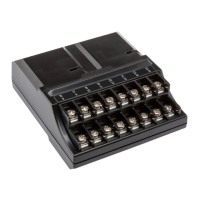
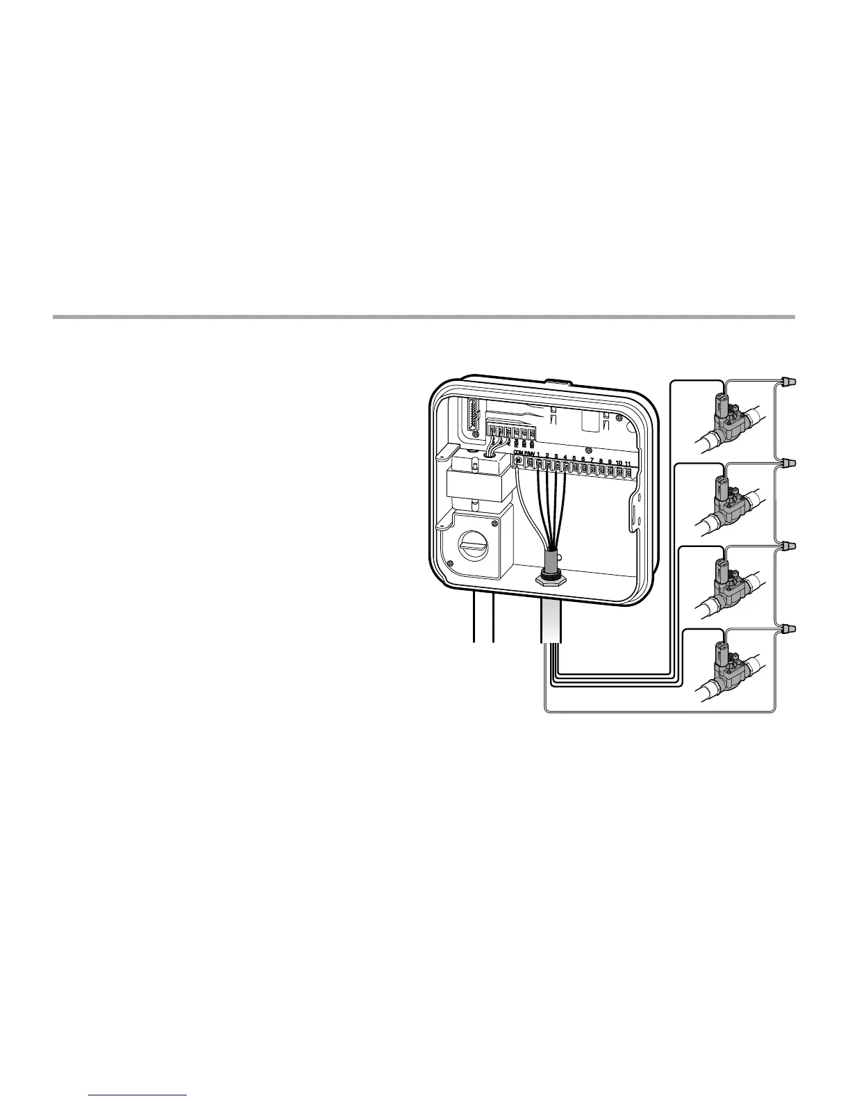
Connecting Station Wires
1. Route valve wires between control valve location
and controller.
2. At valves, attach a common wire to either solenoid wire
of all valves. This is most commonly a white colored wire.
Attach a separate control wire to the remaining wire
of each valve. All wire splice connections should be
done using waterproof connectors.
3. Route valve wires through the conduit and attach conduit
to one of the openings on the bottom of the cabinet.
4. Strip ½" (13 mm) of insulation from ends of all wires.
Secure the valve common wire to “COM” (Common) terminal.
Attach all individual valve control wires to the appropriate
station terminals.
COM
1
2
3
4

Other manuals for Hunter Pro-C

Questions and Answers:

Question and Answer IconNeed help?

Do you have a question about the Hunter Pro-C and is the answer not in the manual?

Hunter Pro-C Specifications

General IconGeneral
Start Times Per Program4
Warranty2 years
Cycle + SoakYes
DisplayLCD
Housing MaterialPlastic
Zones6, 8, 12, 16 (depending on model)
Indoor/OutdoorIndoor
MountingWall-mount
Electrical Input120V AC, 60Hz
Transformer Output24V AC
Number of Stations6, 8, 12, 16 (depending on model)
Wireless CapabilityNo

Related product manuals