4
SRR COMPONENTS (CONTINUED) .................................................
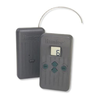
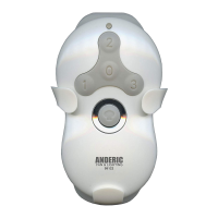
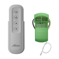
RECEIVER
10. Control Button – Hold button down when
plugging Receiver into SmartPort
®
when
programming a new address.
11. SmartPort Outlet (Male) – Outlet on back
of Receiver that plugs into the SmartPort
harness.
12. Antenna – Receives signals from Transmitter
from up to 450’.
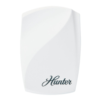
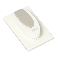
SmartPort
®
13. SmartPort Outlet (Female) – Outlet on
front of SmartPort
®
that plugs into the SRR
Receiver or other Hunter product.
14. Rubber Cover – Protects SmartPort from dirt
and weather.
15. Control Wires – Red, white, and blue wires
that connect to the terminal strip area of the
controller.