FUEL SYSTEM
G
7
– Mount the spring, washer and the O-ring on the
mixture control screw (1) and turn the mixture control
screw all the way in to the stop.
–Now unscrew the mixture control screw the number of
turns written down during disassembly.
NOTE: Basic carburetor setting: see Technical
specifications.
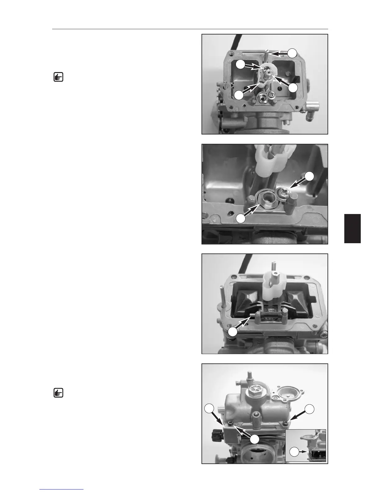
– Mount the idling jet (2), starting jet (3) and needle jet
together with the main jet (4).
– Insert the needle valve seat (5) in the hole and fix with
the screw (6).
– Position the float and the float needle valve and mount
the float hinge pin (7).
– Check the float level (see page G13).
– Mount the float chamber together with the gasket,
position the attachment for the adjusting screw (8) and
fix the float chamber with the screws (9).
NOTE: When mounting the float chamber, make
sure that the push rod (10) on the accelerator
pump slides into the hole.
1
2
3
4
5
6
10
7
9
9
8