ELECTRIC SYSTEM
F
7
IGNITION SYSTEM
General information
The measurements described below will only detect
serious defects.
Short circuits in the coil that lead to a weak ignition spark
or poor generator capacity can only be established on an
ignition test stand.
In case of a defect, check the cable and the plug and
socket connections in the ignition system first.
Always pay attention to the right measuring range for the
digital multimeter when measuring
CHECKING THE STATOR AND PULSE
GENERATOR
Use an ohmmeter to perform the following
measurements:
NOTE: the measurements must be performed
at a temperature of 20° C, otherwise the
readings will deviate significantly.
Replace the stator if one of the measured
values deviates significantly from the setpoint
value.
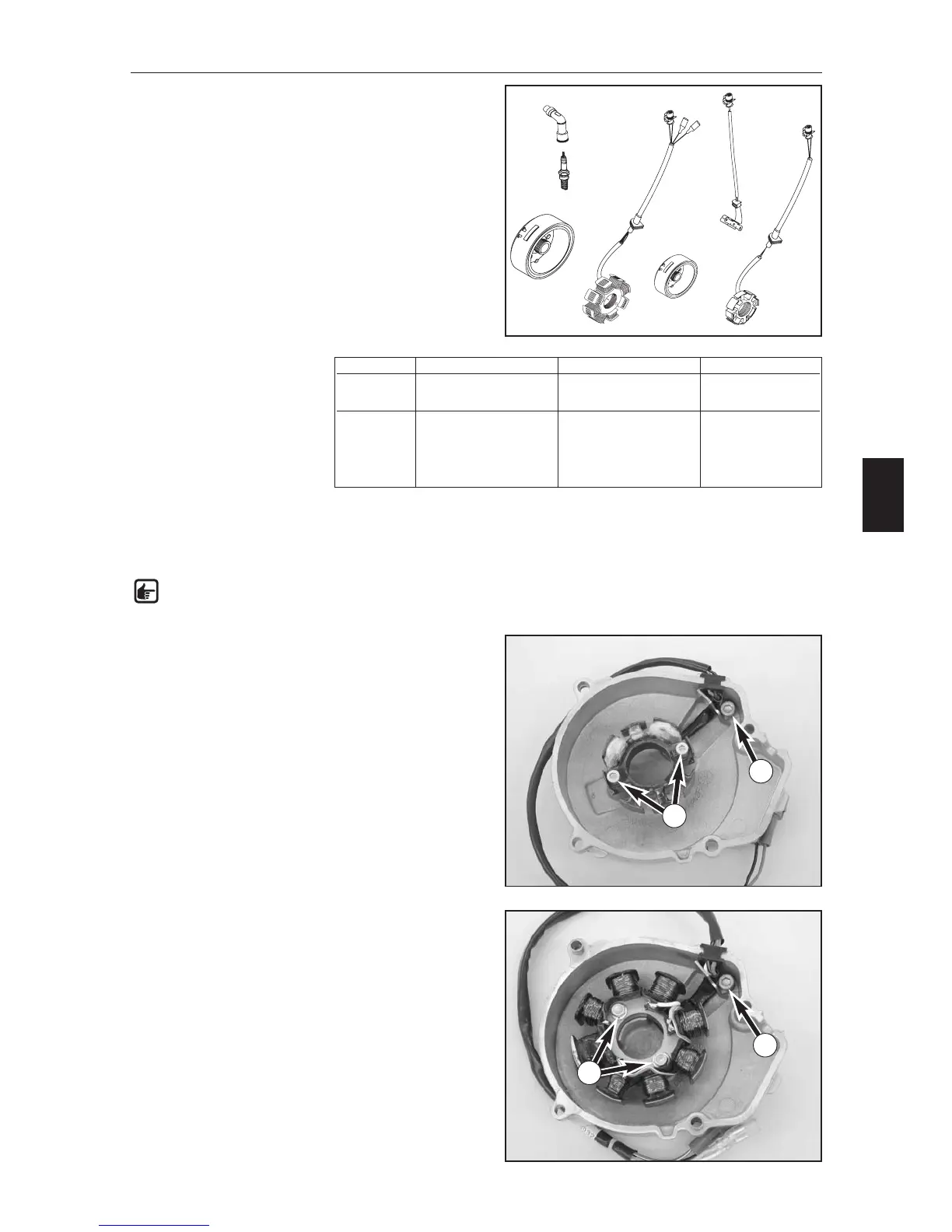
REPLACING THE STATOR IN THE FC
MODELS (4K-3A)
– Remove bolt (1) and the retaining bracket.
–Remove the 2 bolts (2) and take the stator out of the
ignition cover.
–Place a new stator in the ignition cover.
–
Degrease the thread of all 3 bolts and apply Loctite 243.
– Mount the bolts and tighten to 6 Nm.
– Run the wiring harness stress free and fix with the
retaining bracket. Don't forget the cable socket.
REPLACING THE STATOR IN THE FE AND
FS MODELS (4K-3B)
–Remove the bolt (3) and the retaining bracket.
–Remove the 2 bolts (4) and take the stator out of the
ignition cover.
–Place a new stator in the ignition cover. Degrease the
thread of all 3 bolts and apply Loctite 243.
– Mount the bolts and tighten to 8 Nm.
– Run the wiring harness stress free and fix with the
retaining bracket.
Ignition Measurement Cable colors Resistance
4K-3A Pulse generator coil red – green 100 Ω
± 20 Ω
Stator black/red – red/white 26 Ω ± 5,2 Ω
4K-3B Pulse generator coil red – green 100 Ω
± 20 Ω
Stator black/red – red/white 15 Ω ±3 Ω
Charging coil ground – yellow 0,65 Ω ±0,15 Ω
white – yellow 0,16 Ω ±0,03 Ω
1
2
3
4