ASSEMBLING THE ENGINE
E
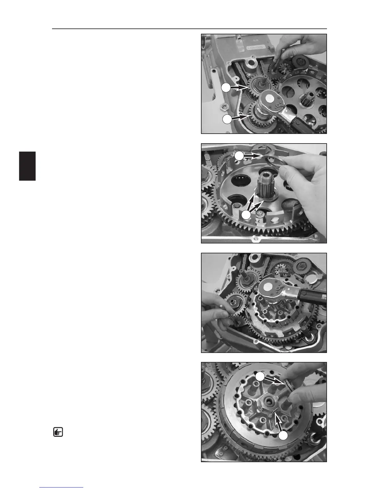
10
–Make sure the marks on the primary pinion and the
idler shaft gear are aligned and loosen the crankshaft
locking bolt 580.30.080.000.
– Lock the primary pinion (1) with the special tool
800.29.004.000 (gear segment) as shown in the photo,
apply Loctite 2701 to the thread of the nut M16x1
(30 mm) and tighten to 110 Nm.
– Lock the idler shaft (2) with the special tool
800.29.004.000 (gear segment) as shown in the photo,
apply Loctite 2701 to the thread of the nut M16x1
(30 mm) and tighten to 110 Nm.
–Place both semiwashers (3) in the groove of the
transmission main shaft and secure with the stepped
disk (4).
–Slip on the driver and lock washer, apply Loctite 243 to
the nut (27 mm) and screw on.
– Insert the clutch holder 800.29.003.000 with into the
outer clutch hub with at least 6 clutch sleeves, lock the
outer clutch hub with the gear wheel segment
(800.29.004.000) as shown in the photo and tighten
the nut to 120 Nm.
– Remove the clutch holder and bend up the the lock
washer (5) of the nut.
– Insert all of the clutch sleeves, fix with some grease if
necessary.
–Starting with one of the clutch disks, alternately insert
8 steel and 7 lining disks in the outer clutch hub,
ending with a clutch disk on top.
–Mount the push rod and the pressure piece (6).
NOTE: insert the thinner end of the push rod
into the pressure piece.
5
3
4
6
1
2