English - 15
1. FUNCTION
The loop signal's reception and amplification in the
mower can also vary by +/- 10% from one mower to
another. This means that at the same point in an
installation one mower may show A=250 and another
A=275. The charging station's circuit board and the
mower's loop sensor can also show some variation
between different machines.
This means that the Automower
®
(not 210 C) will not
follow the boundary wire at the same distance
everywhere along the loop, even if the set corridor
width is the same. The mower will, for example, take a
short cut in corners and not always be able to
negotiate passages.
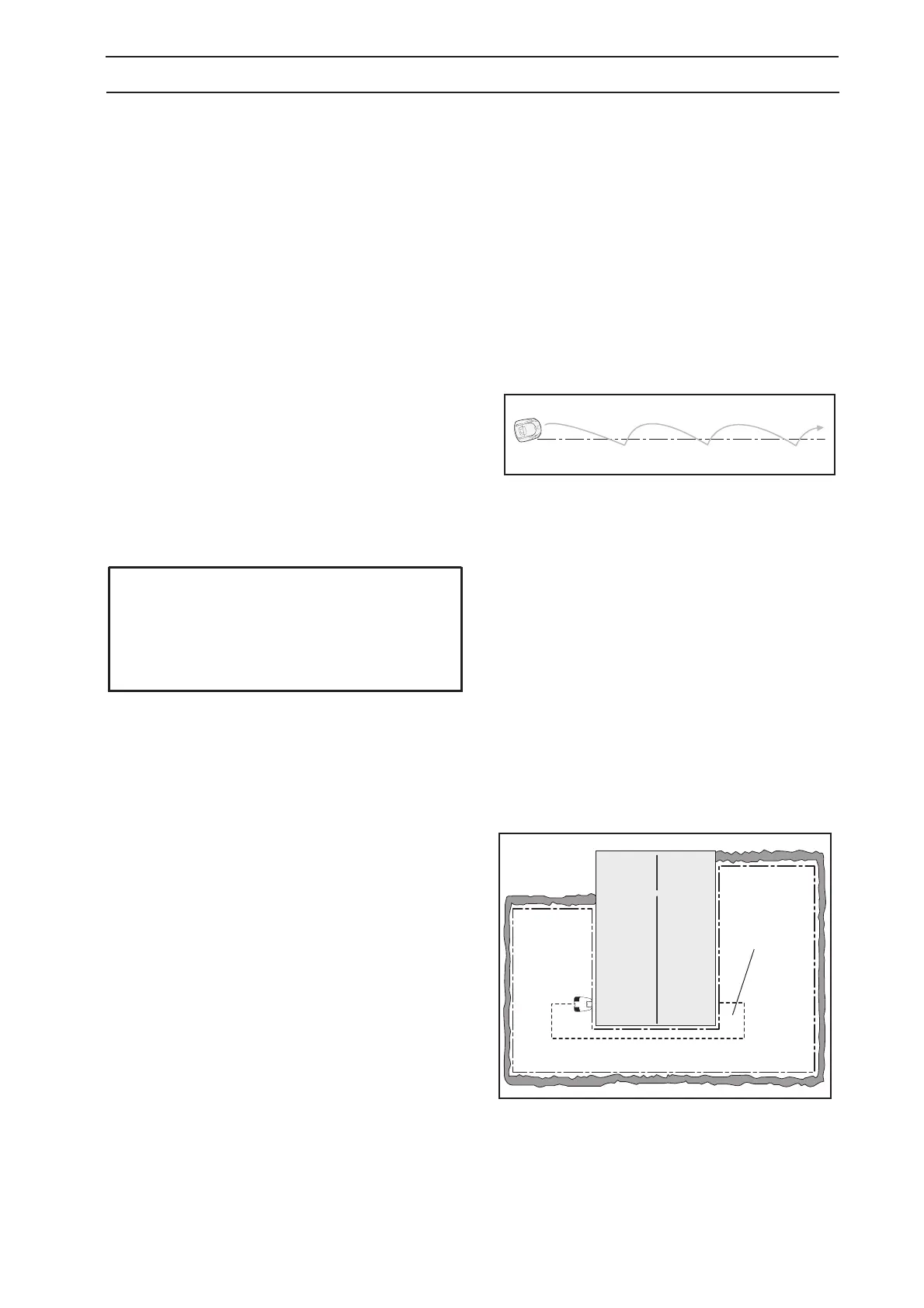
Should the Automower
®
(not 210 C) not find the right
loop signal strength when searching for the charging
station, it will look for the strength by running in a saw
tooth pattern along the boundary wire and in this way
search the area closest to the loop. The behaviour is
recognised through the Automower
®
running for a
short distance, stopping, searching, running for a short
distance again, stopping, searching, running for a short
distance again, stopping, searching and so on.
If the Automower
®
(not 210 C) does not find the right
loop signal strength when it leaves the charging station
to follow the loop to a remote area, it will start to mow
directly instead.
1.8.2 Guide loop
This section does not apply to 210 C.
The guide wire together with the part of the boundary
wire that makes up the return to the charging station
is known as the guide loop. The current in the guide
loop always goes to the left in the connection
between the guide wire and the boundary wire. The
signal from the guide wires are called Guide 1 and
Guide 2 (Guide 2 only applies to 230 ACX, Solar
Hybrid and 260 ACX).
The strength of the Guide signal varies like the
A-signal depending on the distance to the guide wire.
Inside the guide loop the signal is positive and its
strength diminishes the further from the cable you
come. Outside the guide loop the signal is negative
and its strength diminishes more rapidly. The area
inside the guide loop is called the guide area.
Automower
®
always follows on the left-hand side of the
guide wire in the direction towards the charging
station, i.e., the mower follows the negative value on
the Guide signal.
IMPORTANT INFORMATION
The solution to the problem above is to
increase the corridor width for the boundary
wire. The mower then searches for a lower
signal level.
Saw tooth pattern
Guide area
 Loading...