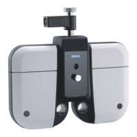
30 Digital Refractor CDR-9000
Step 1 Check the instruments and its accessories listed in 5.4 and prepare them f
or installation.
Step 2 Connect the Digital Refractor to the Junction Box (JB) with 24-pin DVI int
erface cable. Be sure not to connect or disconnect instruments to the jun
ction Box while the power is on.
Step 3 Connect the Operation Panel (OP) to the Junction box with 15-pin D-SUB
interface cable in the 15-pin connector.
Step 4 If the terminator is, connect it to the 4-pin connector named “Terminator”
of the Junction box.
Step 5 Connect chart-presenting device to the Junction box with 4-pin CAN interf
ace cable.
Step 6 Connect the power cord to the Junction Box. Before turning on the power,
make it sure to check the voltage setting of the Junction Box.
Step 7 Turn on the power of the chart-presenting device.
Step 8 Turn on the power switch of the Junction Box.
Step 9 Wait until the Digital Refractor finishes initialization sequence.
Do NOT use other cables except supporting cables(24-pin DVI cable, 1
5-pin D-SUB cable, 4-pin cable…).