Digital Refractor CDR-9000 209
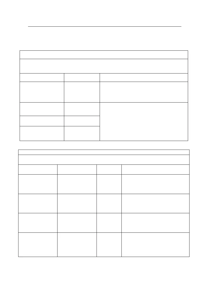
Table 1:Guidance and manufacturer’s declaration – electromagnetic emissions
The CDR-9000 is intended for use in the electromagnetic environment specified below. The cust
omer or the user of the CDR-9000 should assure that it is used in such an environment.
Electromagnetic environment - guidance
The CDR-9000 uses RF energy only for its intern
al function. Therefore, its RF emissions are very l
ow and are not likely to cause any interference i
n nearby electronic equipment
The CDR-9000 is suitable for use in all establish
ments other than domestic and those directly co
nnected to the public low-voltage power supply
network that supplies buildings used for domesti
c purposes
Harmonic emissions
IEC 61000-3-2
Voltage fluctuations/
Flicker emissions
IEC 61000-3-3
Table 2:Guidance and manufacturer’s declaration – electromagnetic immunity
The CDR-9000 is intended for use in the electromagnetic environment specified below. The custo
mer or the user of the CDR-9000 should assure that it is used in such an environment.
Electromagnetic environment - guida
nce
Electrostatic
Discharge(ESD)
IEC 61000-4-2
Floors should be wood, concrete or
ceramic tile. If floors are covered wit
h synthetic material, the relative hum
idity should be at least 30%.
Electrical fast transie
nt/burst
IEC 61000-4-4
±2 kV for power su
pply lines
±2 kV for
power supp
ly lines
Mains power quality should be that
of a typical commercial or hospital e
nvironment
±1 kV lines to lines
±2 kV lines to eart
h
±1 kV lines
to lines
±2 kV lines
to earth
Mains power quality should be that
of a typical commercial or hospital e
nvironment.
Voltage dips, short
interruptions and vo
ltage variations on
power supply input
lines
<5% U
T
(>95% dip in U
T
)
For 0,5 cycle
40% U
T
(60% dip in U
T
)
<5% U
T
(>95% dip
in U
T
)
For 0,5 cycl
e
Mains power quality should be that
of a typical commercial or hospital e
nvironment. If the user of CDR-9000
requires continued operation during
power mains interruptions, it is reco
 Loading...