Pg 3.25 S23P
BLADE GUIDE ADJUSTMENT
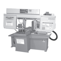
At the bottom of the guide arms are the carbide blade guide assemblies, the
photo below shows the carbide locking handle. These assemblies will need to be
adjusted occasionally as the carbide pads become worn. To adjust properly,
follow this simple procedure. Loosen the hex nut on the locking handle with a 9/16
wrench and turn the handle clockwise until it rests against the coolant tap on the
idler guide arm or the roll pin on the drive guide arm. Turn the set screw clock
wise with a 3/16 allen key until tight and then loosen 1/8 of a turn and tighten the
hex nut. This should put just enough pressure on the blade to permit you to push
the blade down approximately 1/8".
Idler guide arm carbide
locking handle in the
locked position.
BLADE BRUSH ADJUSTMENT
The S-23P leaves the factory with the blade brush adjusted for maximum life of the
brush. This setting places the ends of the blade brush wires so as to contact the blade at
the bottom of the blade gullets. The plastic drive wheel that is driven by the drive wheel
face should be held against the blade face with the minimum force that is necessary. As
the blade brush wears it is necessary to periodically readjust it.
As shown, there are two springs on socket head screws holding the brush assembly
against the blade. There is also an adjusting socket set screw with a hex nut on it.
Loosen the hex nut with a 9/16" wrench and turn the set screw counter clockwise with a
3/16" allen key. This will move the brush closer to the blade. Adjust the set screw so that
the brush cleans to the bottom of the blade gullets and tighten the hex nut.
Blade brush adjusting
screw & hex nut.
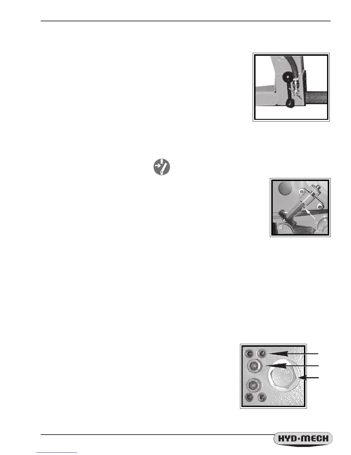
ANGLE BRAKE ADJUSTMENT
The clamping force on the swivel brake can be adjusted to ensure that the Head is held securely and does not
move during cutting. The brake handle should be adjusted so that it does not "bottom out" or hit it's movement limit,
yet holds the head securely.
ANGLE BRAKE ADJUSTMENT PROCEDURE
STEP 1 Loosen locking cap screws "B" with a 1/4 allen key.
STEP 2 Tighten all 4 set screws "A" until snug with a 5/32" allen key.
STEP 3 Back out the "A" screws 1/4 of a turn.
STEP 4 Tighten the locking cap screws "B".
STEP 5 Swing the head to 45
o
and back to ensure that the head moves
freely and does not bind on the pivot surfaces. Continue to step 6 if
necessary.
STEP 6 Adjust the clamping force bolt "C" with a 3/4" wrench. If not
tightened enough, the locking handle will "bottom out" and not hold the
head firmly.
A
C
Angle Brake
Adjustment Screws.
B
 Loading...