1.5
WIRING CONNECTIONS
After the machine is levelled and anchored the necessary power hook-up needs to be performed. In order to provide safe
operation as well as to prevent potential damage to the machine, only qualied personnel should make the connections.
BEFORE START-UP THE FOLLOWING TWO POINTS SHOULD BE
CHECKED
1. Signs of damage that may have occurred during shipping to
the electrical cables and the hydraulic hoses.
2. The hydraulic oil level is between the upper and lower levels
on the gauge.
As supplied, the machine is set to run on three phase voltage as indi-
cated on the serial plate and voltage label.
During the initial hook-up, it is very important to check that the phase
order is correct. This is indicated by the hydraulic system pressure gauge
registering a pressure rise and the blade running in a counter clockwise
direction. If the hydraulics do not register an immediate pressure rise,
SHUT THE HYDRAULICS OFF and change the phase order.
ATTENTION: Running the hydraulics “backwards” can damage the hydraulic pump!
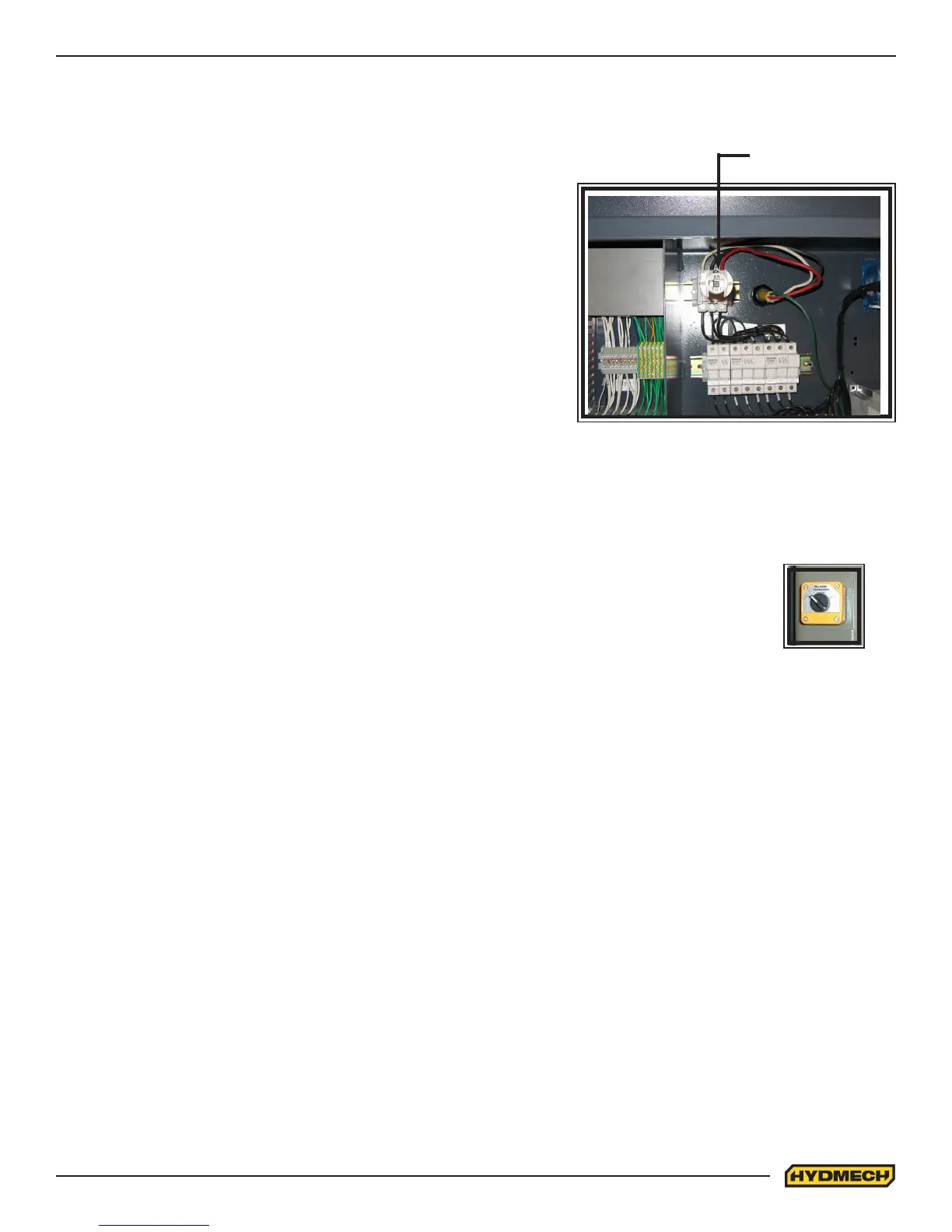
Power connection to the machine is made to the L1, L2, L3 and ground terminals located inside the control panel as
shown in the photo.
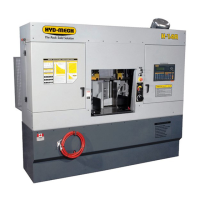
BLADE TENSION CHECK
When the machine is rst started, the blade position must be checked. Open the door at the top of the
head and see that the blade has not moved o of the wheel. It should not be overhanging the wheel
more than 1/4”. If it is consult “Blade Tracking” in Section 3 If it has stayed in it’s correct position, then
check that the blade tension switch is in the “+” position and close the door.
EARTH GROUNDING PROCEDURE
1. The customer is to provide and install a ground rod approx. .60 (15mm) diameter, copper clad steel, to be driven
no less than 8’ (2.5m) into the ground, no more than 10’ (3m) away from control enclosure.
2. The ground rod is to be connected to customer’s in plant ground system. This connection shall be made directly
at the ground rod. (If applicable).
3. It is desirable that the overall resistance to ground measured at the ground rod does not exceed 3 ohms. Cus-
tomer is advised to consult local power company for further information on grounding.
4. The ground rod is to be connected to the ground terminal in the control enclosure using insulated, stranded 8
gauge copper wire.
5. An additional point to check is to ensure continuity of all ground within the control enclosure. Start with the main
power entrance ground terminal where the internal ground conductors should originate and then connect to, the
DIN terminal strip, control transformer, and the lid of control enclosure. Also, the PLC and Interface units should
have their own ground conductors connected to one of the main ground terminals.
6. A properly functioning ground system will:
- provide safety for personnel.
- ensure correct operation of electrical/electronic apparatus.
- prevent damage to electrical/electronic apparatus.
- help dissipate lightning strikes.
- divert stray radio frequency (RF) energy from electronic/control equipment.
Blade tension
switch
Power connection terminal
L1, L2, L3, G
(Cover in place)
L1, L2, L3