2.11
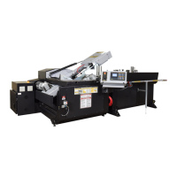
COOLANT FLOW
A generous ow of coolant should be applied in order to increase pro-
duction and blade life. The machine is provided with a control switch
on the operator panel and an independently controlled coolant spout.
This spout should always ood the blade with coolant. Slight adjust-
ment may be required when changing the blade speed. A properly
adjusted ow of coolant should cover the blade which in turn will carry
it into the cutting area. A ow adjusting tap is shown on the Console
side in the photo.
NOTE: When cutting materials that do not need coolant (cast iron)
some coolant ow is required to provide blade lubrication in order to
prevent blade scoring by the carbides.
HYDRAULIC CHIP CONVEYOR (optional)
An option available with the V18 is the hydraulic chip conveyor drive which provides an easier means of clean-
ing out the chips that accumulate while cutting. A Chip Conveyor control switch for the hydraulically driven chip
conveyor is located on the operator control panel.
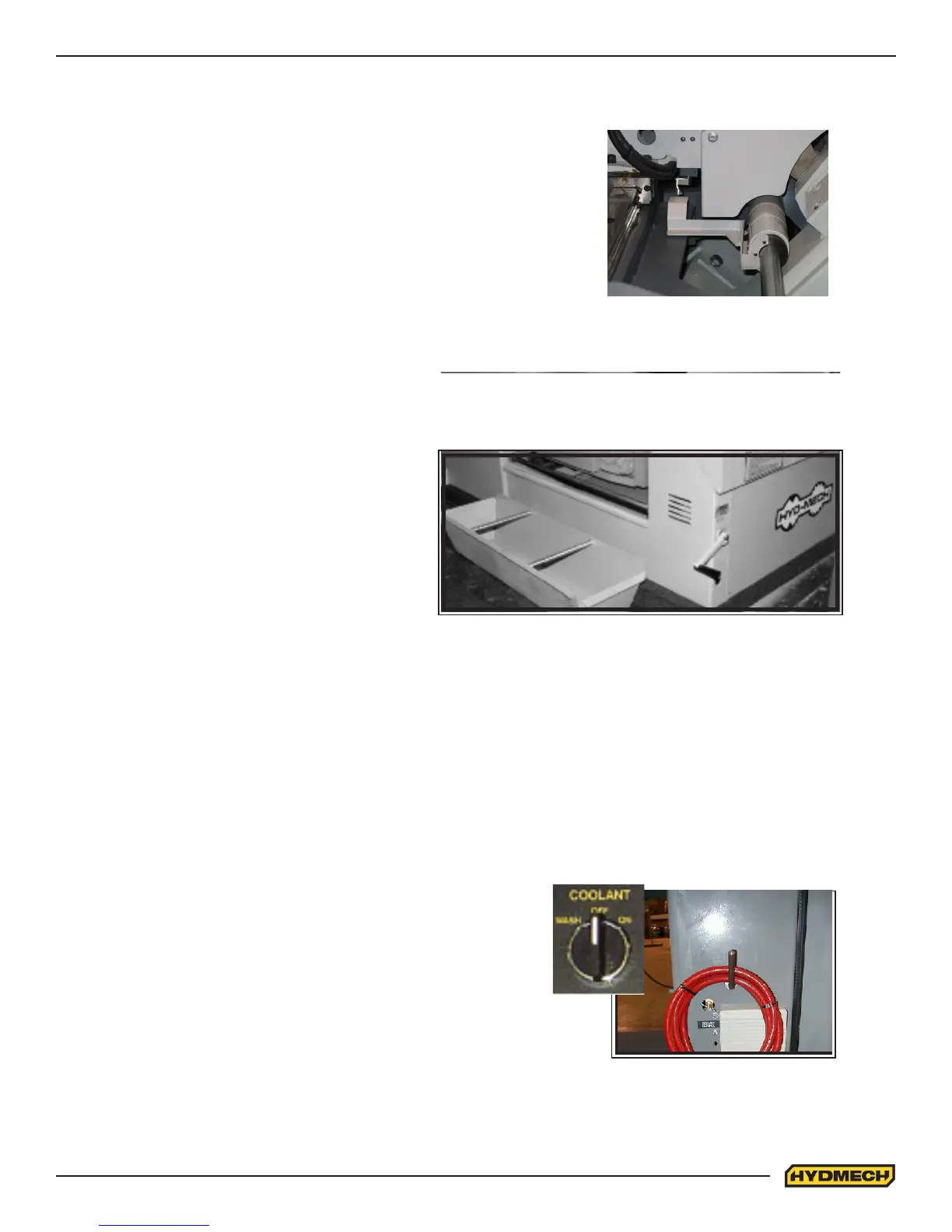
CHIP CONVEYOR (optional)
The chips generated while sawing can be removed
from the bottom of the machine with the help of the
optional chip conveyor. Rotation of the chip convey-
or crank will operate the conveyor in the direction of
rotation of the crank. A chip bucket is included with
the chip conveyor option. The crank handle and chip
bucket are shown here.
Manual chip conveyor handle and chip bucket.
MECHANICAL CONTROLS
Coolant adjusting tap and
wash hose
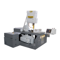
HEAD FORWARD LIMIT SETTING
The Head Forward Limit is factory set and under normal operating conditions
should not need to be reset.
TO SET LIMIT:
If adjustment of the Shaft Collar is necessary, the Head Forward Limit is an
assembly on the vise cylinder rod. Loosen the set screw that allows setting
of the limit switch actuator, and adjust according to your needs. The photo
shows the Head Forward limit switch assembly. This assembly will be on
the same side of the head as the in-feed conveyor.
Head forward limit switch