2.10
ADDITIONAL CUTTING SETUP EXAMPLES
EXAMPLE # 2
Material Round Steel Tube SAE 4320 - Hardened to 35 RC ( 325 Bhn )
Dimensions - 6” O.D. x 4” I.D. (150mm O.D. x 100mm I.D.)
STEP I Eective Material Width: 4 1/2” (.75 X 6) 114mm (19 x 6)
STEP 2 Feed Force limit setting for 6” Diameter material.
Refer to Feed Force Limit, Setting in Step 2
STEP 3 Optimum blade pitch (TPI): 3/4 T. P. I.
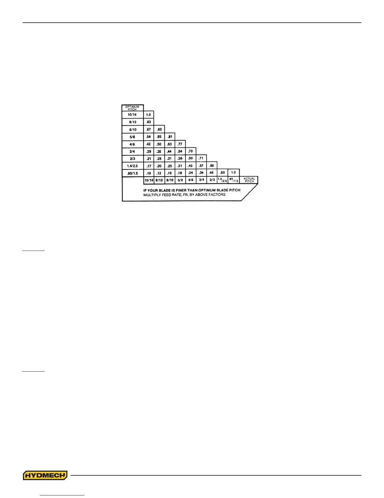
Actual blade pitch on the saw: 4/6 T. P. I.
STEP 4 Optimum blade speed for 4 1/2” eective 225 ft/min (70m/min) material width
Blade speed reduced by hardness factor : 225 ft/min X .60 = 135ft/min or
(70m/min x .60 = 42m/min)
STEP 5 Feed Rate for 3/4 TPI blade: 1.8 in/min (45mm/min)
Feed Rate for 4/6 TPI blade: 1.8 in/min X .70 = 1.3in/min
(reduced by ner than optimum blade pitch factor) or (45mm/min x .70= 31.5mm/min)
EXAMPLE # 3
Material Bundle - Low carbon steel 2” x 2” Tube with 1/4” wall, 12 piece bundle
(50mm x 50mm with 6mm wall)
Dimensions: 6” x 8” (150mm x 200mm)
STEP I Eective Material Width: 5” ( .6 X 8” ) 120mm (.6 x 200)
STEP 2 Feed Force limit setting for 8” Diameter material.
Refer to Feed Force Limit, Setting in Step 2
STEP 3
Optimum blade pitch (TPI): 3/4 T. P. I.
STEP 4 Optimum blade speed for 5 “ eective material width: 320 ft/min (100m/min)
STEP 5 Feed Rate for 3/4 TPI blade: 4.0 in/min (100mm/min)
Feed Rate, continued
If the saw is tted with a blade coarser than optimum (e.g.. 1.4/2.5 TPI) we can still use the graph, but we go to the 1.4/2.5
curve. As a result we nd that the FEED RATE is decreased to 1.3 in/min (133mm/min) for this blade. If however, the ma-
chine is tted with a ner than optimum blade (e.g. 3/4 TPI) we use the graph for the optimum blade as before, and then
use a multiplier given by the table below.
NOTE: Use the following chart when cutting solids. For structurals, see
“CUTTING STRUCTURALS”
in STEP 2.