2.9
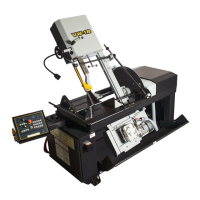
For Example #1, it is known from Step 3 that optimum blade pitch is 2/3, and from Step 4 that blade speed, is 200 ft/min
(60mm/min). From the Graph on the left, the FEED RATE is determined in the following way:
- On the horizontal axis (blade speed axis), nd 200 ft/min(60mm/min).
- Find the point where a ver tical line from 200 ft/min (60mm/min) would intersect the 2/3 blade pitch curve.
- From this intersection point run horizontally left to the ver tical (FEED RATE) axis, to ar rive at 1.8 in/min (45mm/min)
FEED RATE. Thus 1.8 in/min (45mm/min) is the FEED RATE for cutting 8” (200mm) diameter 1045 Carbon Steel when
the optimum 2/3 pitch blade is used.
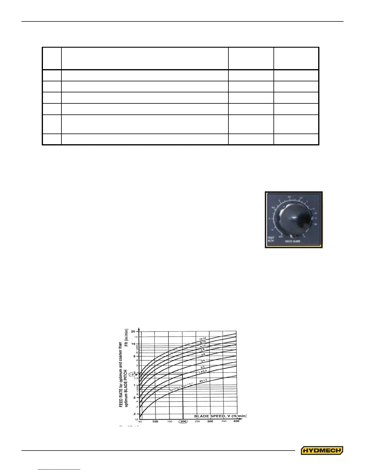
STEP 5, DETERMINE FEED RATE SETTING, FR (in/min) (mm/min).
FEED RATE is the speed at which the blade travels through the work-piece.
The FEED RATE Knob controls FEED RATE of the blade descent in the range 0 to 15 in/
min (380mm/min). The FEED RATE should be adjusted only in one direction (from “O” to
required value). If you go too far, go back to “O” and come back up. To set FEED RATE for
particular cutting situations use the Graph below, which represents the relationship be-
tween FEED RATE, blade speed and blade pitch.
Feed Rate Knob
The following table gives examples of the optimum blade speeds for dierent materials.
NO. Materials
Optimum
Blade Speed
ft/min
Optimum
Blade Speed
m/min
1 5" (125mm) diameter solid medium carbon steel 225 70
2 10" (250mm) I-Beam 270 90
3 4" x 4" (100mm x 100mm) Rect tube 1/4" (6mm) wall 325 110
4 4" 9100mm) 400 stainless steel 140 45
5
2" x 2" (50mm x 50mm) Rect tube 1/4" (6mm) wall
bundle 5 x 5 pcs 10" x 10" (500mm x 500mm)
300 100
6 3" x 3" (75mm x 75mm) Inconel 60 20