MAINTENANCE
HPR260 Manual Gas Instruction Manual 5-45
Automatic chopper and current sensor tests during power-up
Turn ON the system. When the preflow starts, the contactor will close and the system will
automatically test the choppers and current sensors. The system closes the contactor and turns
on chopper 1 at 90% duty cycle. The chopper will charge the surge capacitor on the I/O board
(PCB 6). The current that charges the capacitor should be between 10 amps and 35 amps.
Error code 105 will appear in the LED display if the current is < 10 amps or there is no
feedback on current sensor 1 (CS1). Error code 103 will appear in the LED display if the
current is > 35 amps.
If chopper 1 passes the test, the system will repeat the test for chopper 2, and current sensor 2
(CS2). Error code 106 will appear in the LED display if the current is < 10 amps. Error code
104 will appear in the LED display if the current is > 35 amps.
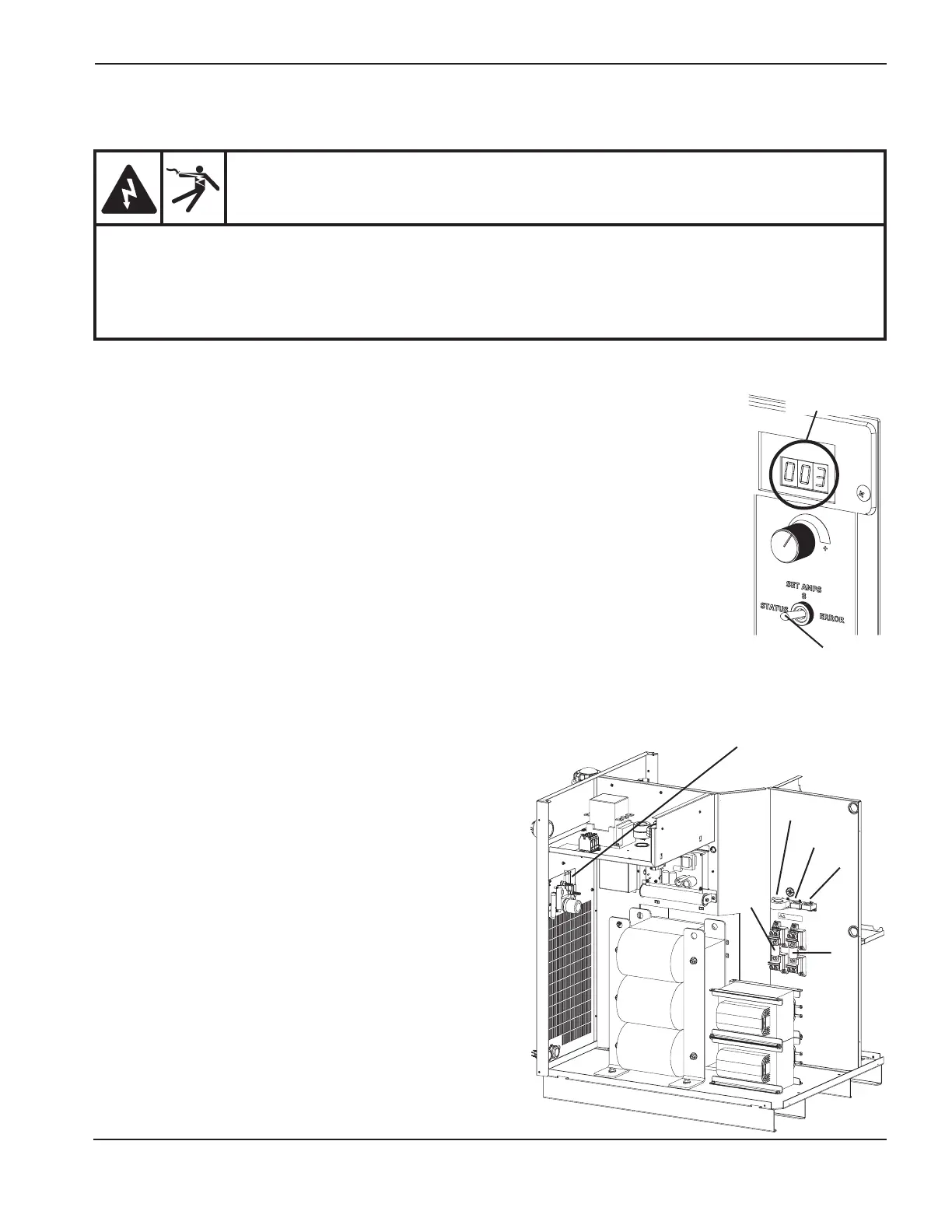
Place the toggle switch in the ERROR position if the system completes the power up
sequence. If the system shows error code 003 the test passed. The choppers and current
sensors are OK.
If error code number 103, 104, 105, or 106 are displayed, continue with the tests below.
Troubleshooting low-current error codes 105 and 106
1. Verify that the current sensors (CS1 and CS2) and
cables are not damaged.
2. Exchange CS1 and CS2. Replace the faulty sensor if
the error code is not displayed again.
3. Measure the resistance between wire 38 and wire 39
on PCB6 with a meter. The value should be increasing
as the capacitor charges. Replace PCB6 if a constant
value is seen.
4. Check for loose wires or shorts from the chopper to
PCB6.
5. Check for 220 VAC to 1A, 1B, and 1C on the chopper
when the contactor closes.
6. Verify that the fuses (F3 and F4) are in good working
condition.
Chopper tests
WARNING
SHOCK HAZARD: Use extreme care when working near the chopper modules. Each large electrolytic
capacitor (blue-cased cylinder) stores large amounts of energy in the form of electric voltage. Even if
the power is off, dangerous voltages exist at the capacitor terminals, on the chopper, and the diode
heatsinks. Never discharge any capacitor with a screwdriver or other implement … explosion,
property damage and/or personal injury will result.
CS1
CS3
F3
I/O board
(PCB6)
CS2
F4
Toggle
switch
LED display
4
 Loading...


