Service Manual
7. Baseband Section
7.1 Power Section
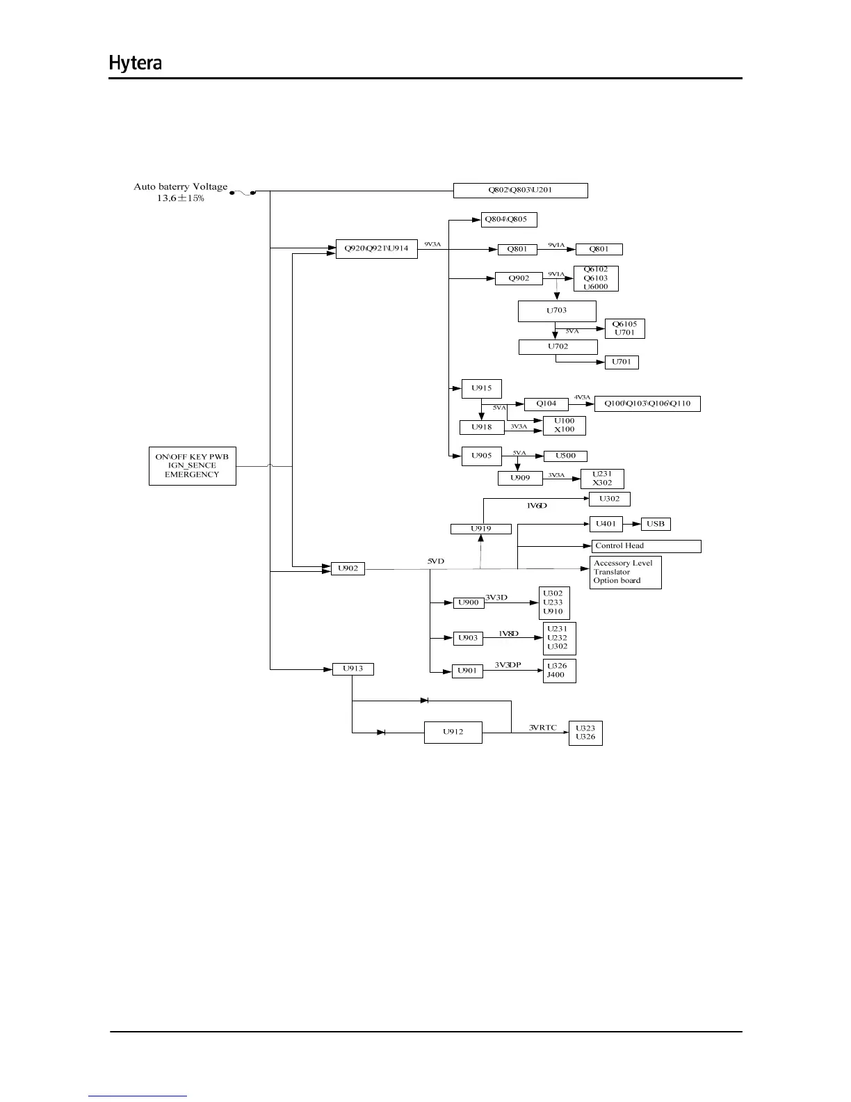
Figure 7-1 Diagram of Power Distribution
Both the baseband control IC and the RF section can convert the supplied voltage to an appropriate one
via the voltage converter.
Supply for RF: U914, Q920 and Q921 supply power for the RF section by high current PNP
transistor and comparator, which can work as LDO (Low Dropout Regulator).
Supply for FGU: U918 and U915 supply 3.3V and 5V respectively to U100.
Supply for Baseband: The processor U302 is supplied by 3.3V (U900), 1.8V (U903) and 1.6V
(U919); the memory is supplied by 3.3V (U900) and 1.8V (U903) respectively; the audio processor
IC is supplied by 3.3V (U900&U909) and 1.8V (U903); the DAC is supplied by 5V (U905) and 3.3V
(U900).
EXT_SWB+: Q909.
9

 Loading...