Service Manual
procedures are completed.
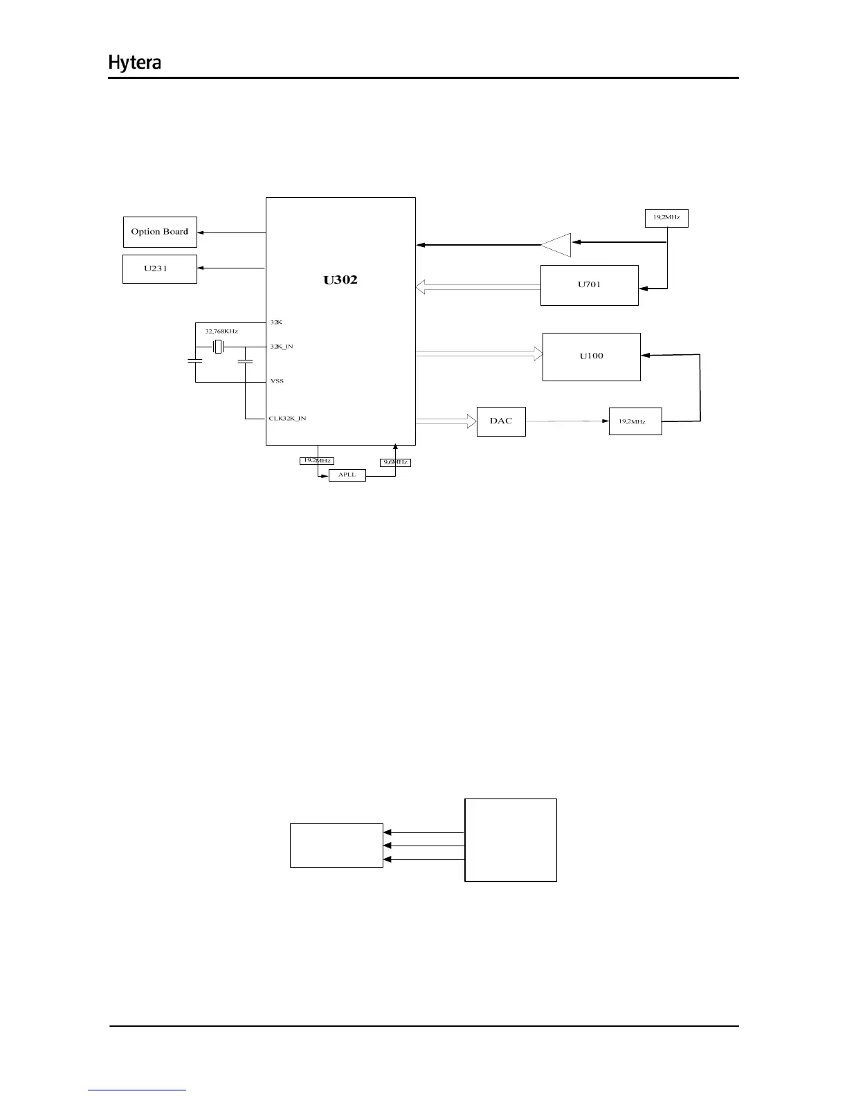
7.3 Clock
Figure 7-2 Diagram of Clock Distribution
7.3.1 Input Clock
The 32K clock provided by X375 is mainly used for timing and sleeping of the system. Its frequency
(32.768 kHz) is divided by U302 (32768 times in all) to 1Hz for counting seconds. The system clock
(19.2MHz) is generated by an external crystal oscillator.
7.3.2 Output Clock
The baseband outputs 3 clock signals fed to U231, U100 and Option Board respectively.
7.4 Interface Distribution
7.4.1 Serial Peripheral Interface (SPI)
SPIF.SCK
SPIF.DOUT
U302
SPIF.CS2PE
U701
PC
PD
Figure 7-3 Diagram of SPI Interface
SPI of U302 operates in Master Mode, and is controlled by MPU or DMA. In this case, U302 can provide
4 chip select signals, of which CS2 is used to control the IF processor U701.
7.4.2 MCSI Interface
11

 Loading...