Service Manual
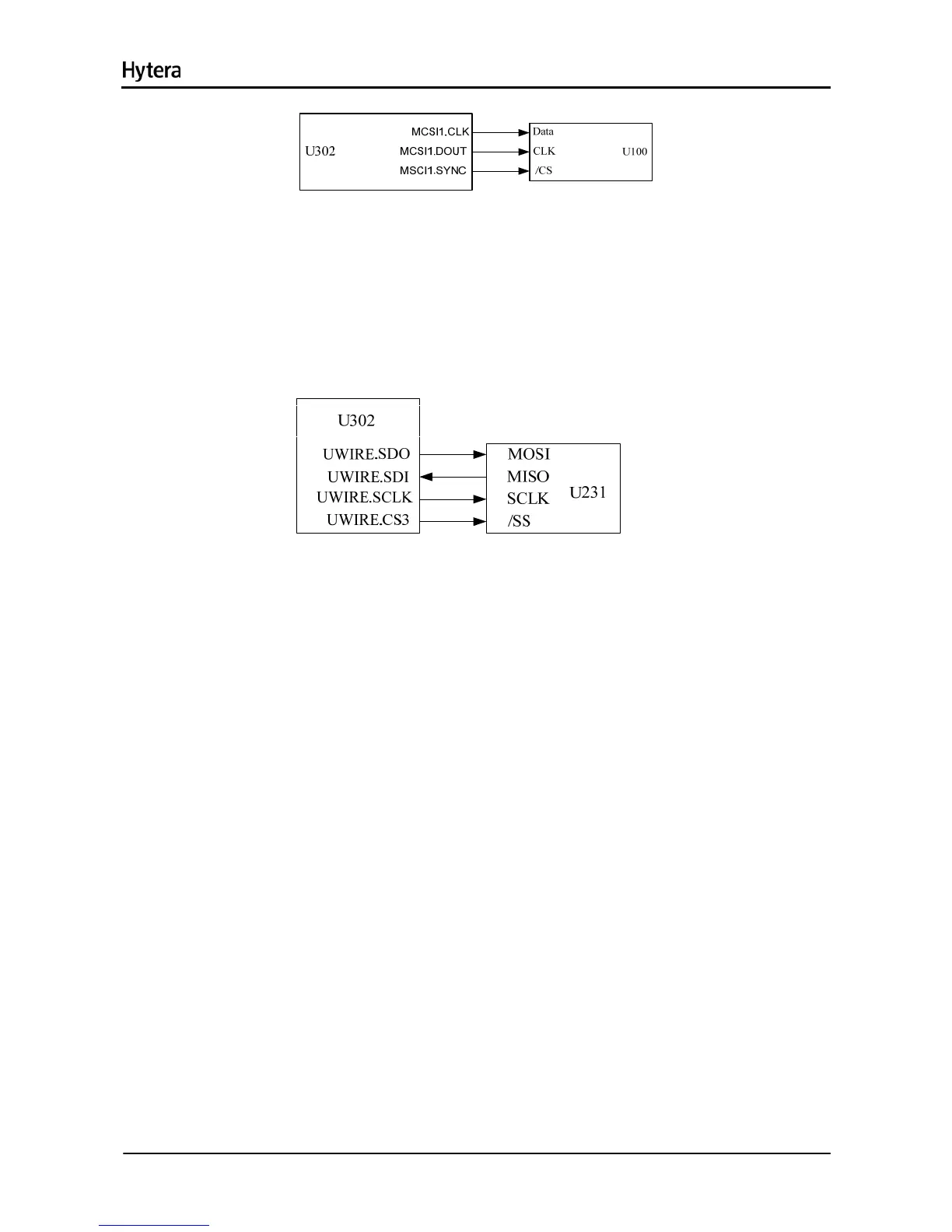
Figure 7-4 Diagram of MCSI Interface
When U302 is communicating with U100, it works in Master Mode with clock frequency of up to 9.6MHz.
U100 uses MCSI synchronization as chip select signal and MCSI1.DOUT as data cable to configure its
register.
7.4.3 MICROWIRE Interface
Figure 7-5 Diagram of MICROWIRE Interface
The MICROWIRE interface can accommodate 4 external devices at most, generally transmitting control
and status messages of external devices, and reading data from ROM. Its maximum clock frequency is a
quarter of system clock frequency. In this case, MICROWIRE is used to configure or read from the audio
processor. It requires chip select signal CS3.
7.4.4 Serial Synchronous Interface (SSI)
12

 Loading...