Service Manual
11.1.9 Output Power Control
The TX power is controlled by U801. The forward power is applied to the directional coupler, to output a
voltage that can represent the forward power. The voltage together with the preset voltage feeds to U801
to output a voltage VGG, which can control both gate voltage and gain of Q804 and Q805, ensuring a
constant power output.
11.1.10 Thermal and Over-voltage Protections
The circuit consists of thermistor RT804 and resistor R884. The output voltage is proportional to the
detected temperature. Both the voltage used for temperature detection and the threshold voltage are fed
into the operational amplifier U803, to output a voltage signal that is in proportion to the detected
temperature. Afterwards, the voltage is applied to software for judgment, and then the preset voltage will
be subsequently changed to reduce the TX power, and to protect the PA from over-heating.
11.1.11 Pressure Pad Switch
The power control circuit includes a pressure pad switch SW1, which is controlled by the conductive
rubber part mounted on the top cover. If the switch is turned off, VGG will become low, and no power will
be output from PA. Otherwise, PA will work normally.
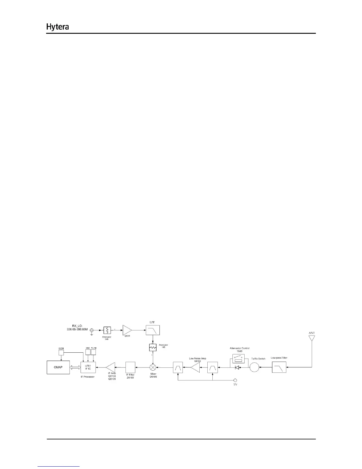
11.2 Receiver Circuit
The receiver utilizes double conversion superheterodyne technique. The first IF is 73.35MHz and the
second IF is 2.25MHz. The first local oscillator signal is from the PLL circuit U100, and the second local
oscillator signal (71.1MHz) from the PLL circuit U701. The major units are BPF, LNA, mixer, IF filter, IF
amplifier and IF processor.
Figure 11-2 Diagram of Receiver Circuit
11.2.1 Receiver Front-end
RF signals feed to the low-pass filter to remove out-of-band signals, and are applied to the two-stage
29

 Loading...