Service Manual
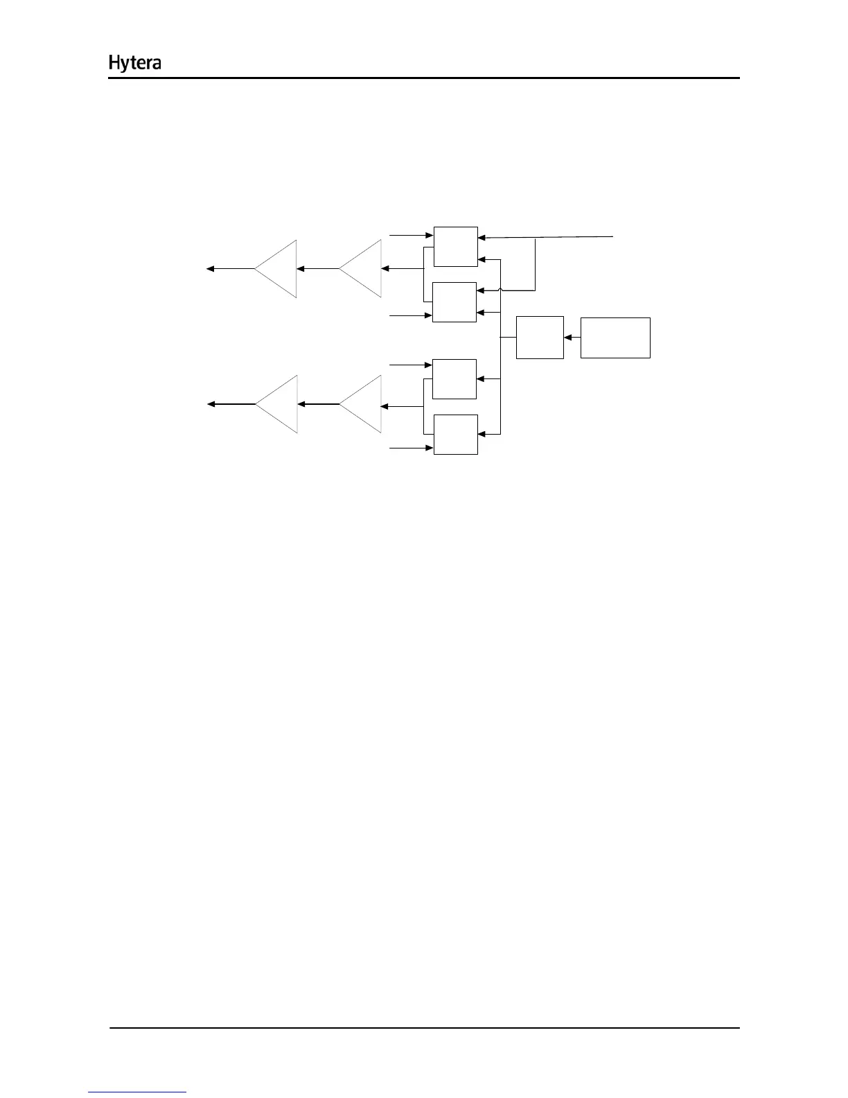
oscillators. There are four VCOs in all: two VCOs (Q100 and Q103) used to transmit excitation signals
and the other two VCOs (Q106 and Q110) to receive LO signals. U302 controls the operating frequency
of the VCO. Q102 and Q107 constitute the buffer amplifiers for the transmitter circuit, while Q111 and
Q109 for the receiver circuit. The digital-to-analog converter (U500) modulates the TX oscillator signal.
PLL IC (U100)
Q103
LPF
Q110
Q100
Q106
Q102
Q111
Q107
MOD
RX_H_VCO
RX_L_VCO
TX_H_VCO
TX_L_VCO
Q109
TX PA
RX Lo
Figure 11-5 Diagram of VCO
32

 Loading...