Service Manual
7.6 PCB Difference
The UHF1 PCB has three versions: D, F and H.
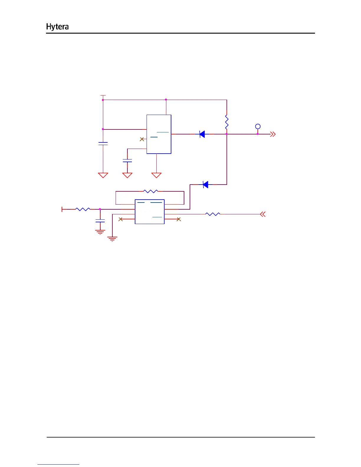
The watchdog circuit (in the figure below) is added in version F.
19
U906
RESET IC
MR
1
VCC
2
GND
3
PFI
4
PFO
5
WDI
6
/RST
7
WDO
8
R920 0
C978
0.1u
R983 0
RST_CTRL
R923 0
3V3D
D912
MBRM120LT1G
12
D913
MBRM120LT1G
12
R932
4.7K
C941
0.15u
U910
SENCE
5
VDD
6
RSET
1
GND
2
CT
4
MR
3
/PRST1
1
C937
1000p
3V3D
/PRST
Figure 7-10 Watchdog Circuit
Watchdog circuit
The watchdog circuit is used to prevent the radio from damage due to OMAP malfunction. If the program
works properly, U302 feeds pulse signal (25ms) to the watchdog circuit through RST_CTRL. Otherwise,
this pulse signal will be terminated and delayed for more than 1.6s so that U906 generates the reset
signal to reset OMAP.
Compared with version D & F, the difference in version G lies with the audio amplifier, which applies
TDA7297SA instead of TDA7297D.

 Loading...