Service Manual
16
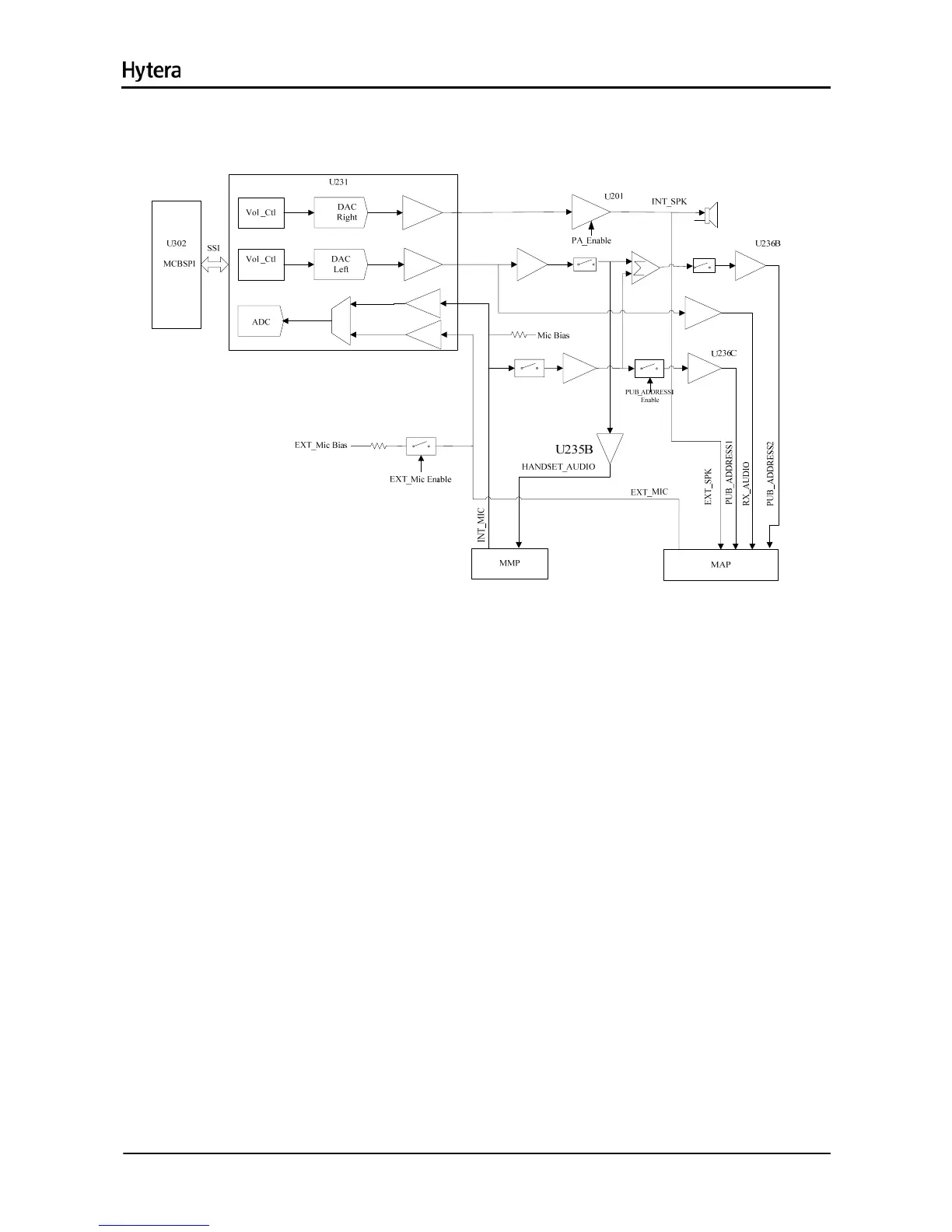
7.5 Audio Section
Figure 7-9 Diagram of Audio Section
7.5.1 RX Audio Circuit
U302 sends digital audio to the audio processor codec via the SSI bus of MCBSP1. This bus is
composed of CLKX, FSX, DX and DR. It sends the demodulated PCM audio signal to the codec, and
adjusts the signal to appropriate amplitude according to the volume (RMS should be 80mv when
frequency is 1 KHz and deviation is 3 KHz). Then the codec converts PCM data into analog audio data
via DAC. U231 provides two outputs: SPK1 and SPK2. SPK1 is amplified by U238 and then is fed to the
PA U201, to derive two outputs of received audio, which will be applied to the front panel speaker and
further development interface respectively. SPK2 is amplified and divided into the four paths of signal
HANDSET_AUDIO, RX_AUDIO, PUB_ADDESS1 and PUB_ADDESS2. The first two paths are
amplified by U235, and the last two paths are amplified by U236. Output of HANDSET_AUDIO,
PUB_ADDESS1 and PUB_ADDESS2 are controlled by Q231, Q235 and Q233 respectively.
7.5.2 TX Audio Circuit
The audio processor U231 has two MIC inputs: the internal MIC and external MIC. The internal MIC is
connected to the MICIN_HND of U231, and is combined with AUX1 to provide differential input. After
9.3V is divided by R255 and R264, a bias voltage of about 7V is provided to the front panel MIC. The

 Loading...