Service Manual
24
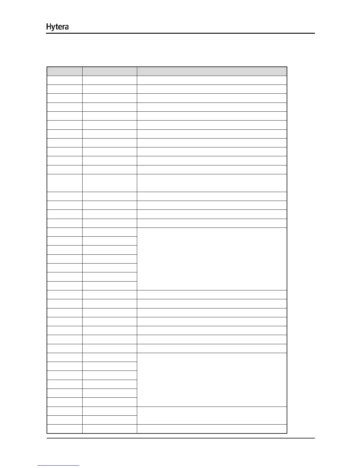
10. Interface Definition
J404: to front panel jack
Pin No. Name Function
1 INT_MIC Audio input
2 MIC_GROUND Audio input ground
3 ACC_IO1 Accessory identifier pin 1
4 USB_VBUS USB power supply
5 HOOK HOOK
6 PTT PTT
7 USB_D- USB data cable D-
8 USB_D+ USB data cable D+
9 ACC_IO2 Accessory identifier pin 2
10 UART2_RXD_A Volume control port
11 UART2_TXD_B
12
HANDSET_AUDI
O
Audio signal output by accessory
13 SPKR1+ Speaker audio signal cable+
14 SPKR1- Speaker audio signal cable-
15 5VD Power supply
16 PRST Reset signal
17 KB_C0
18 KB_C1
19 KB_C2
20 KB_C3
21 KB_R0
22 KB_R1
23 KB_R2
Matrix keyboard
24 CSLED Backlight control IC chip select
25 CLOCK Backlight control IC clock
26 DATA Backlight control IC data
27 OE_LCD LCD read enable
28 WE_LCD LCD write enable
29 CS2_LCD LCD chip select
30 F_A1_LCD LCD register enable
31 F_D7
32 F_D6
33 F_D5
34 F_D4
35 F_D3
36 F_D2
LCD data bus
37 F_D1
38 F_D0
LCD data bus
39 GND Ground

 Loading...