Service Manual
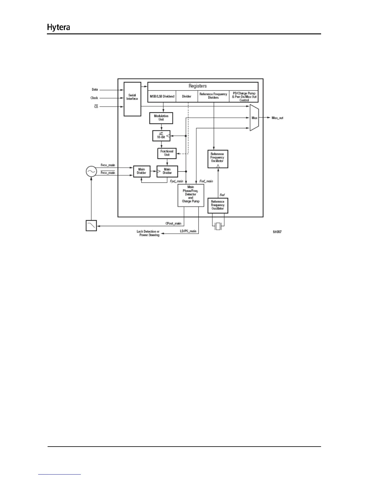
The PLL IC (U100) is a fractional frequency divider. The logic IC U101 and U102 work with the PLL IC
(U100) to achieve locking.
Figure 14-4 Diagram of PLL IC
The 19.2MHz frequency generated by the reference oscillator goes into the PLL IC for division,
generating the reference frequency. Meanwhile, the frequency generated by VCO goes into PLL IC
(U100) for frequency division. The resulting frequency will be compared with the reference frequency in
terms of phase difference in the phase detector. After comparison, the resulting frequency is converted
to CV voltage via the loop filter, to control and lock the frequency.
14.3.4 VCO
The VCO is composed of transistors (Q100, Q103, Q106 and Q110), varactors and four Colpitts
oscillators. There are four VCOs in all: two VCOs (Q100 and Q103) used to transmit excitation signals
and the other two VCOs (Q106 and Q110) to receive LO signals. U302 controls the operating frequency
of the VCO. Q102 and Q107 constitute the buffer amplifiers for the transmitter circuit, while Q111 and
Q109 for the receiver circuit. The digital-to-analog converter (U500) modulates the TX oscillator signal.
236

 Loading...