3.5 Input and Output Signal Process for Field Network
143
3.5 Input and Output Signal Process for Field Network
(1) I/O Signal Timings
When any of the control signal is turned ON to perform the operation of the robot cylinder using
the PLC's sequence program, the response (status) is returned to the PLC. The maximum
response time is expressed using the following formula.
The value is constant regardless the number of composition axes.
Max. response time (msec.) = Yt + Xt +(3 × Mt) + Response process time (operation time, etc.)
Yt : Master Station → Slave Transmission Delay Time
Xt : Slave → Master Station Transmission Delay Time
Mt = MSCON internal communication sending time (Ttx) + MSCON internal communication
receiving time (Trx)
Refer to the instruction manual of the mounted PLC for the master station → slave transfer
delay time (Yt) and the slave → master station transfer delay time (Xt).
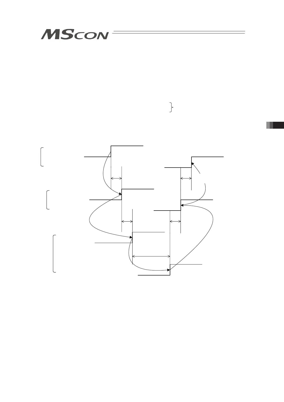
Master → Remote I/O Station
Transmission Delay Time (Yt) *1
Response Process
Time *2
PLC Sequence Program
Control Signal
Status Signal
Gateway
Control Signal
Status Signal
Controller
Control Signal
Status Signal
*1 Refer to PLC Manual
*2 Varies depending on the content of control
Remote I/O Station → Master
Transmission Delay Time (Xt) *1
Ttx to Mt+Ttx Trx to Mt+Trx
Mt = max.10ms
(data being processed at once for six axes)
Field Network Transmission Delay Time