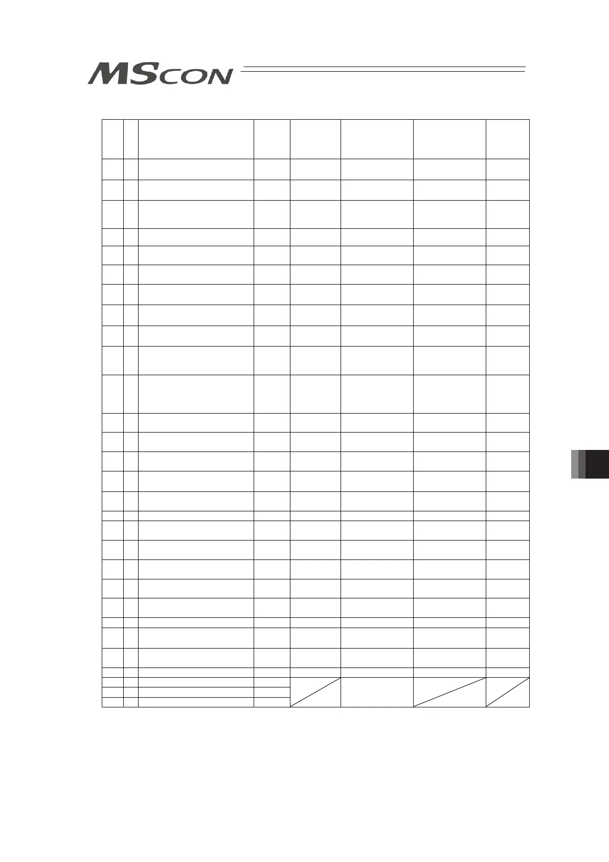
249
Parameter List (continued)
No.
Category
Name Symbol
Unit
(Note 1)
Input Range
Default factory
setting
Relevant
sections
22 C Home Return Offset Level OFST
mm
[deg]
0.00 to 9999.99
In accordance
with actuator
(Note 2)
7.2 [16]
23 B Zone 2 Positive Side ZNM2
mm
[deg]
-9999.99 to
9999.99
Actual stroke on
positive side
(Note 2)
7.2 [1]
24 B Zone 2 Negative Side ZNL2
mm
[deg]
-9999.99 to
9999.99
Actual stroke on
negative side
(Note 2)
7.2 [1]
25 A PIO Pattern Selection IOPN - 0 to 2, 4, 5 and 8 8 7.2 [18]
26 B PIO Jog Velocity IOJV
mm/s
[deg/s]
1 to Actuator’s
max. speed
100 7.2 [19]
27 B Movement Command Type FPIO -
0 : Level
1 : Edge
0 7.2 [20]
31 C
Velocity Loop Proportional
Gain
VLPG - 1 to 27661
In accordance
with actuator
(Note 2)
7.2 [21]
7.3
32 C Velocity Loop Integral Gain VLPT - 1 to 217270
In accordance
with actuator
(Note 2)
7.2 [22]
7.3
33 C Torque Filter Time Constant TRQF - 0 to 2500
In accordance
with actuator
(Note 2)
7.2 [23]
7.3
34 C Push Velocity PSHV
mm/s
[deg/s]
1 to actuator's
max. pressing
speed
In accordance
with actuator
(Note 2)
7.2 [24]
35 C Safety Velocity SAFV
mm/s
[deg/s]
1 to 250
(maximum speed
for the actuators
with 250 or less)
100 7.2 [25]
36 B
Auto Servo-motor OFF Delay
Time 1
ASO1 sec 0 to 9999 0 7.2 [26]
37 B
Auto Servo-motor OFF Delay
Time 2
ASO2 sec 0 to 9999 0 7.2 [26]
38 B
Auto Servo-motor OFF Delay
Time 3
ASO3 sec 0 to 9999 0 7.2 [26]
39 B
Position Complete Signal
Output Method
(Note 3)
FPIO -
0: PEND
1: INP
0 7.2 [27]
40 C Home-return Input Disable FPIO -
0: Enabled
1: Disabled
0 7.2 [28]
46 B Velocity Override OVRD % 1 to 100 100 7.2 [29]
47 B PIO Jog Velocity 2 IOV2
mm/s
[deg/s]
1 to Actuator’s
max. speed
100 7.2 [19]
48 B PIO Inching Distance IOID
mm
[deg/s]
0.01 to 1.00 0.1 7.2 [31]
49 B PIO Inching Distance 2 IOD2
mm
[deg/s]
0.01 to 1.00 0.1 7.2 [31]
50 C
Load Output Judgment Time
Period
LDWT msec 0 to 9999 255 7.2 [32]
52 B
Default Acceleration/
Deceleration Mode
CTLF - 0 to 2 0 (Trapezoid) 7.2 [33]
53 B Default Stop Mode CTLF - 0 to 3 0 (Not applicable) 7.2 [34]
54 C Current Control Width Number CLPF - 0 to 4
In accordance
with actuator
(Note 2)
7.2 [35]
55 B
Position Command Primary
Filter Time Constant
PLPF msec 0.0 to 100.0 0.0 7.2 [36]
56 B S-motion Rate SCRV % 0 to 100 0 7.2 [37]
62 B Pulse Count Direction FPIO
65 B Electronic Gear Numerator CNUM
66 B Electronic Gear Denominator CDEN
For future
extension use.
Unavailable
Note 1: The unit [deg] is for rotary actuator. It is displayed in mm in the teaching tools.
Note 2: The setting values vary in accordance with the specification of the actuator. At shipment, the
parameters are set in accordance with the specification.