50
2.3.3 Actuator Connection
To the encoder connector and motor connector on each actuator, connect the relay cables.
[Refer to the Note.]
Check in the instruction manual of each actuator for the details of the relay cables.
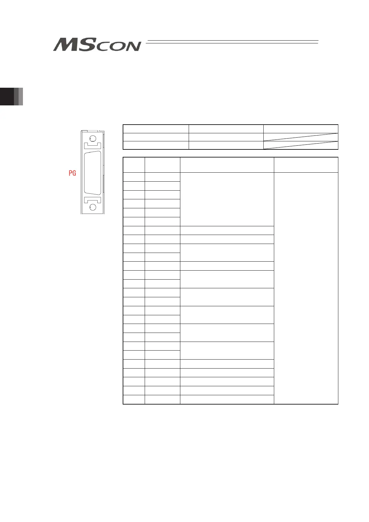
(1) Encoder Connector
Encoder Connector Model Remarks
Cable Side 10126-3000PE
Controller Side 10226-52A2PL
Pin
No.
Signal
Name
Contents Applicable Cable
1 NC
2 NC
3 NC
4 NC
5 NC
6 NC
Unconnected
7 SRD+ Serial Encoder Communication+
8 SRD- Serial Encoder Communication-
9 LC_SD+
10 LC_SD-
For future extension (Reserved)
11 NC Unconnected
12 24VOUT
13 0V
24V power supply for sensors
14 BATT
15 BATTGND
Battery power supply for ABS
16 VCC
17 GND
Encoder Power Supply
18 LC_VCC
19 LC_GND
For future extension (Reserved)
20 BK-
21 BK+
Brake Power Supply
22 NC Unconnected
23 RSV Sensor Input (Reserve)
24 OT Sensor Input (Over Travel)
25 CREEP Sensor Input (Creep Sensor)
26 LS Sensor Input (Limit Switch)
Cable dedicated for
IAI products
PG
Front view of
connector on
controller side