POWER CON
PCON-CB/LC
13
1) Absolute Battery Connector [Refer to Chapter 7]
It is the connector to plug in the enclosed battery if applicable for Simple Absolute Type
(option).
2) Absolute Battery [Refer to Chapter 7]
It is enclosed if applicable for Simple Absolute Type (option).
Use unit by affixing it on the side of PCON body with fabric hook-and-loop fastener or store it
Absolute Battery Unit (option).
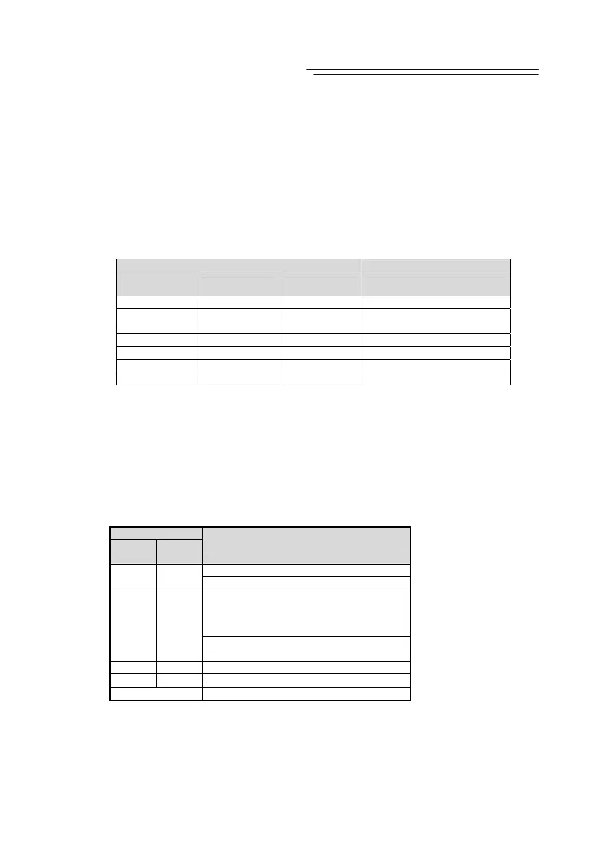
3) Absolute Battery Status Indicator LED [Refer to Chapter 7]
It is equipped if applicable for Simple Absolute Type (option).
It displays the status such as battery charge condition and error generation.
{ : Illuminating × : OFF
LED Operation status
RDY(GN)/
ALM(RD)
1 (GN/RD) 0 (GN/OR/RD) Description
× × × Control Power OFF
{ (GN) { (GN)
{
(Either color)
Absolute Reset Complete
{ (GN) { (RD)
{
(Either color)
Absolute Reset Incomplete
{ (RD) { (RD)
{
(Either color)
Error occurred.
{
(Either color)
{
(Either color)
{ (GN) Battery Fully Charged
{
(Either color)
{
(Either color)
{ (OR) Battery Charging Operation
{
(Either color)
{
(Either color)
{ (RD) Battery Disconnected
4) PIO Connector/ Fieldbus Connector
PIO Type is equipped with the input and output signal connectors for control and Fieldbus
Type with connectors for each Fieldbus connection.
[Refer to 2.1.2 PIO Pattern Selection and PIO Signal or 2.2.2 I/O Signals in Pulse Train
Control Mode]
[For the details of the Fieldbus, refer to Chapter 4 and the instruction manual for each
Fieldbus.]
5) Controller Status Indicator LED
Following show the controller operation status:
{ : Illuminating × : OFF ☆ : Flashing
LED
SV (GN)
ALM
(RD)
Operation status
Control Power OFF
× ×
Servo OFF
Alarm
(Operation Cancellation Level or more)
Motor Driving Power Supply OFF
×
{
In the Emergency Stop
{
× Servo ON
☆
× During Automatic servo-off
(Note 1)
{ (OR) During initialization after power is supplied
Note 1 Signal during automatic servo-off : [Refer to Chapter 6]
 Loading...


