Chapter 2 Wiring
POWER CON
PCON-CB/LC
67
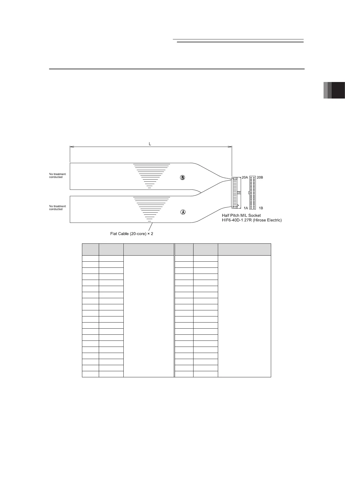
2.3.3 Connection of PIO
Conduct the connection of I/O to the controller is to be carried out using the dedicated I/O cable.
The cable length is shown in the model code of the controller. Please check the controller
model code. There are 2m for standard, 3m and 5m as an option. Up to 10m I/O cables are
sold separately. [Refer to 1.1.5 How to read the model]
Also, the end of the cable harness to be connected to the host controller (PLC, etc.) is just cut
and no treatment is conducted so the wiring layout can be performed freely.
Model : CB-PAC-PIO□□□
(□□□ indicates the cable length L. Example. 020 = 2m)
No.
Cable
Color
Wiring No.
Cable
Color
Wiring
1A BR-1 1B BR-3
2A RD-1 2B RD-3
3A OR-1 3B OR-3
4A YW-1 4B YW-3
5A GN-1 5B GN-3
6A BL-1 6B BL-3
7A PL-1 7B PL-3
8A GY-1 8B GY-3
9A WT-1 9B WT-3
10A BK-1 10B BK-3
11A BR-2 11B BR-4
12A RD-2 12B RD-4
13A OR-2 13B OR-4
14A YW-2 14B YW-4
15A GN-2 15B GN-4
16A BL-2 16B BL-4
17A PL-2 17B PL-4
18A GY-2 18B GY-4
19A WT-2 19B WT-4
20A BK-2
Flat Cable
○
A
(Press Welding)
AWG28
20B BK-4
Flat Cable
○
B
(Press Welding)
AWG28
For the signal assignment of each wire, refer to the following considering the operation mode.
1) Positioner Mode ························ 2.1.3 [4] PIO Circuit
2) Pulse Train Control Mode ············ 2.2.3 [3] PIO Circuit
 Loading...


