Chapter 2 Wiring
POWER CON
PCON-CB/LC
54
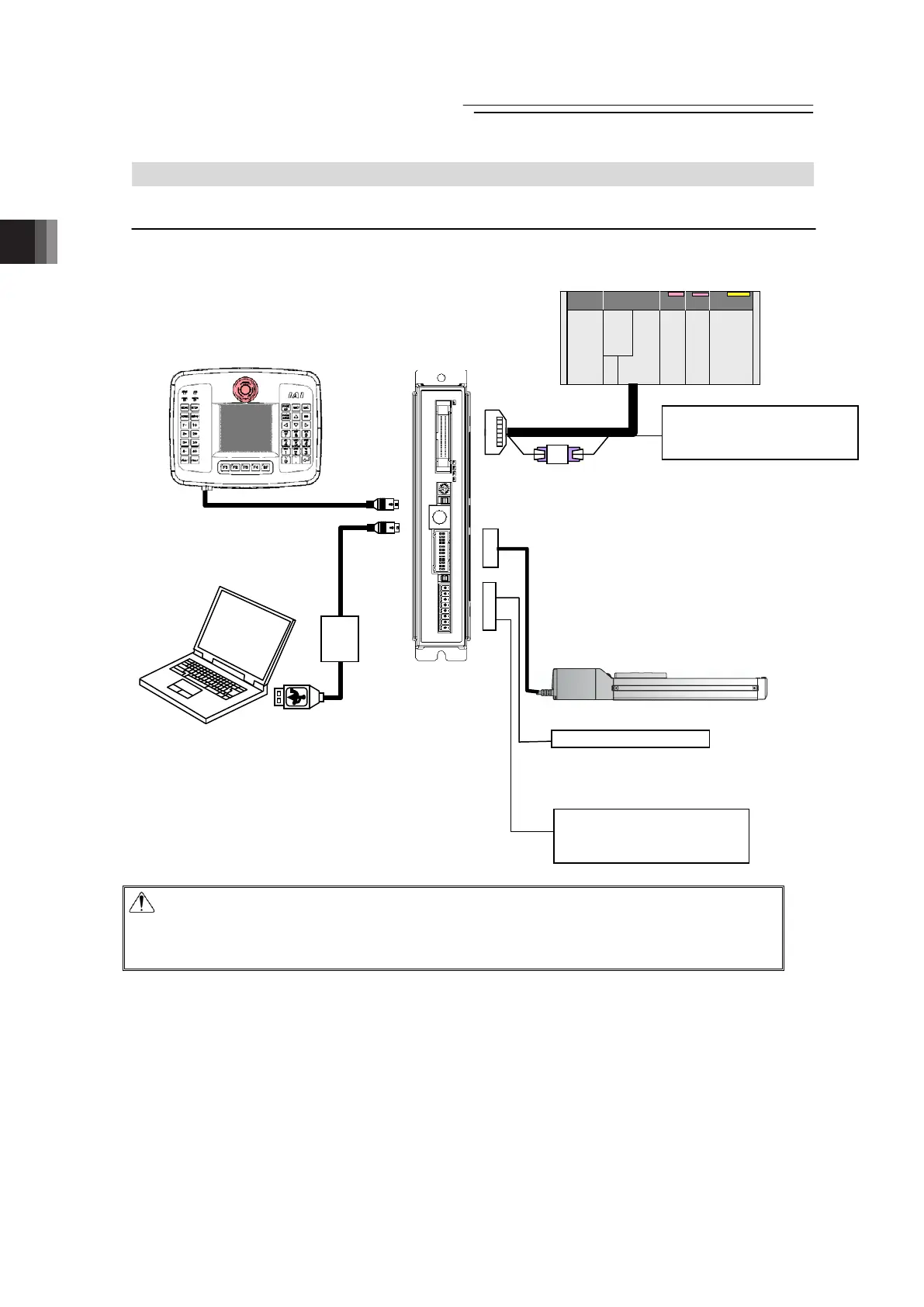
2.2 Pulse Train Control Mode
2.2.1 Wiring Diagram (Connection of Devices)
Caution : Make sure to turn the power to the controller OFF when inserting or removing the
connector that connects the PC software or touch panel teaching.
Inserting or removing the connector while the power is turned ON causes a
controller failure.
Touch Panel Teaching
(to be purchased separately)
PC Software
(to be purchased separately)
ctuato
Host System
(PLC, etc.…Please prepare separately)
Power Source I/O Control
(24V DC
…Please prepare separately)
Emergency Stop Circuit
Control/Driving Power Supply
(24V DC
…Please prepare separately)
K-04
K-04 (to be purchased separately)
Necessary when host positioning unit
is open collector output.
 Loading...


